
Control Systems Fundamentals
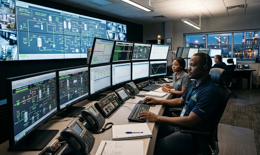
Introduction to Control Systems
A control system is a group of devices and actions used to monitor, compare, and adjust a process so that it operates safely and correctly.
In instrumentation and control, control systems are used to manage process variables such as pressure, temperature, flow, level, speed, position, and quality. These systems help keep plant operations stable, efficient, and safe.
A control system may be simple, such as a thermostat controlling room temperature, or complex, such as a refinery control system managing hundreds of instruments, controllers, valves, motors, alarms, and interlocks.
Why Control Systems Are Important
Control systems help industries operate processes with less manual effort and better consistency.
They are important because they help to:
- Maintain process stability.
- Improve safety.
- Reduce human error.
- Improve product quality.
- Reduce waste.
- Protect equipment.
- Improve energy efficiency.
- Maintain production targets.
- Support automatic operation.
- Alert operators when conditions become abnormal.
Without control systems, operators would need to manually monitor and adjust every process condition, which would be difficult, slow, and risky.
Basic Elements of a Control System
A basic control system includes measuring devices, a controller, and a final control element.
| Element | Function |
|---|---|
| Process | The system or operation being controlled |
| Sensor / transmitter | Measures the process variable |
| Controller | Compares the measured value with the setpoint |
| Final control element | Adjusts the process |
| Signal path | Carries measurement and control signals |
| Operator interface | Allows operators to monitor or adjust the process |
Example:
In a tank level control system, the level transmitter measures the tank level, the controller compares it with the desired level, and a control valve adjusts the inlet or outlet flow.
Common Control System Terms
| Term | Meaning |
|---|---|
| Process variable: PV | The actual measured value of the process |
| Setpoint: SP | The desired value the process should maintain |
| Error | The difference between setpoint and process variable |
| Controller output: OP | The signal sent by the controller to the final control element |
| Manipulated variable: MV | The variable adjusted to control the process |
| Disturbance | Any change that affects the process |
| Final control element | Device that physically changes the process |
| Feedback | Measured process information returned to the controller |
A technician must understand these terms because they appear in control-room displays, PLC programs, DCS graphics, loop diagrams, and maintenance procedures.
Process Variable
The process variable is the actual condition being measured.
Examples:
- Pressure in a pipeline
- Temperature in a heat exchanger
- Flow rate through a pipe
- Level inside a tank
- Speed of a motor
- Position of a valve
- pH of a liquid
The process variable tells the control system what is happening in the process.
Setpoint
The setpoint is the target value the process should maintain.
Example:
If a tank level should remain at 60%, then 60% is the setpoint.
If a boiler pressure should remain at 8 bar, then 8 bar is the setpoint.
The controller compares the process variable with the setpoint and decides whether correction is needed.
Error
Error is the difference between the setpoint and the process variable.
Error = Setpoint − Process Variable
Example:
Setpoint = 80°C
Process variable = 75°C
Error = 80 − 75 = 5°C
The controller uses this error to decide how much correction is needed.
Manipulated Variable
The manipulated variable is the part of the process that is changed to control the process variable.
Examples:
| Process Variable Being Controlled | Manipulated Variable |
|---|---|
| Tank level | Inlet or outlet flow |
| Temperature | Steam flow, cooling water flow, heater power |
| Pressure | Vent valve opening, compressor speed |
| Flow | Control valve position or pump speed |
| Motor speed | Drive output frequency |
The manipulated variable is usually changed through a final control element such as a control valve, actuator, motor drive, damper, or heater.
Final Control Element
The final control element is the device that physically adjusts the process.
Common final control elements include:
- Control valves
- Solenoid valves
- Actuators
- Dampers
- Variable frequency drives
- Motors
- Heaters
- Pumps
- Louvers
- Relays and contactors
The controller sends an output signal to the final control element, and the final control element changes the process condition.
Open-Loop Control
Open-loop control is a control method where the controller sends an output, but it does not use feedback to confirm whether the process reached the desired value.
In an open-loop system, the controller does not automatically correct errors.
Example:
A water pump is switched on for 10 minutes to fill a tank, but there is no level transmitter to confirm the actual tank level. The pump runs for the set time whether the tank is full, half-full, or overflowing.
Open-Loop Control Example
A heater is turned on for 30 minutes to warm a tank.
The system does not measure the actual temperature. It only applies heat for a fixed time.
This is open-loop control because the system does not check whether the required temperature has been reached.
Advantages and Limitations of Open-Loop Control
| Advantages | Limitations |
|---|---|
| Simple design | No automatic correction |
| Lower cost | Cannot respond to disturbances |
| Easy to operate | Less accurate |
| Fewer instruments required | May waste energy or materials |
| Useful for simple tasks | Can become unsafe if conditions change |
Open-loop control may be acceptable for simple or non-critical applications, but it is not suitable where accuracy and safety are important.
Closed-Loop Control
Closed-loop control uses feedback from the process to automatically correct the output.
In a closed-loop system, the process variable is measured and compared with the setpoint. If there is an error, the controller adjusts the final control element to reduce the error.
PID controllers are common feedback controllers, and they use a process variable and setpoint to determine a controller output for variables such as temperature, pressure, and flow.
Closed-Loop Control Example
A tank level should remain at 60%.
- The level transmitter measures the actual level.
- The controller compares the actual level with the setpoint.
- If the level is too low, the inlet valve opens more.
- If the level is too high, the inlet valve closes or the outlet valve opens more.
- The transmitter keeps sending feedback to the controller.
This is closed-loop control because the system continuously checks the process and corrects the output.
Open-Loop vs Closed-Loop Control
| Feature | Open-Loop Control | Closed-Loop Control |
|---|---|---|
| Feedback | No feedback | Uses feedback |
| Error correction | No automatic correction | Automatic correction |
| Accuracy | Lower | Higher |
| Complexity | Simple | More complex |
| Cost | Lower | Higher |
| Response to disturbance | Poor | Better |
| Common use | Simple timing or fixed output tasks | Process control and automation |
Closed-loop control is commonly used in modern process industries because it can respond to changing process conditions.
Feedback
Feedback is the process of sending measured information back to the controller.
Feedback allows the controller to know whether the process variable is above, below, or equal to the setpoint.
Example:
A temperature transmitter sends the actual temperature back to the controller. The controller uses this feedback to decide whether to increase or reduce steam flow.
Without feedback, the controller would not know what is happening in the process.
Negative Feedback
Negative feedback is the most common type of feedback used in industrial control. It reduces the difference between the setpoint and the process variable.
Example:
If temperature is higher than the setpoint, the controller reduces heating.
If temperature is lower than the setpoint, the controller increases heating.
Negative feedback helps stabilise the process.
Positive Feedback
Positive feedback increases the effect of a change. It is usually not used for normal process control because it can make a system unstable.
Example:
If pressure increases and the controller responds by increasing pressure even more, the system may become dangerous.
Positive feedback may exist in special electronic or control applications, but in process control, technicians must understand that wrong signal action can accidentally create unstable behaviour.
Controller Action
Controller action determines how the controller output responds when the process variable changes.
The two common actions are:
| Controller Action | Meaning |
|---|---|
| Direct acting | Output increases when process variable increases |
| Reverse acting | Output decreases when process variable increases |
Correct controller action is important. Wrong action can drive the process in the wrong direction and create instability.
Direct Acting Control Example
A pressure controller opens a vent valve when pressure rises.
- Pressure increases.
- Controller output increases.
- Vent valve opens more.
- Pressure reduces.
This is direct acting because the controller output increases as the process variable increases.
Reverse Acting Control Example
A temperature controller adjusts steam to a heater.
- Temperature increases above setpoint.
- Controller output decreases.
- Steam valve closes.
- Temperature reduces.
This is reverse acting because the controller output decreases as the process variable increases.
On/Off Control
On/off control is the simplest type of automatic control. The output is either fully on or fully off.
Examples:
- A thermostat switching a heater on and off.
- A level switch starting and stopping a pump.
- A pressure switch starting and stopping a compressor.
- A float switch controlling a water tank.
On/off control is simple but may cause the process variable to rise and fall around the setpoint.
On/Off Control Example
A water pump fills a tank.
- Pump starts when level falls below 40%.
- Pump stops when level reaches 80%.
The pump is either on or off. There is no gradual control.
This method is common in simple tank and pump control systems.
Deadband
Deadband is a small range around the setpoint where no control action happens. It helps prevent frequent switching.
Example:
A thermostat is set to 25°C with a deadband of 2°C.
- Heater turns on when temperature falls to 24°C.
- Heater turns off when temperature rises to 26°C.
Without deadband, the heater may switch on and off too frequently.
Modulating Control
Modulating control adjusts the output gradually rather than simply switching on or off.
Examples:
- A control valve opens 30%, 50%, or 75%.
- A variable speed drive changes motor speed.
- A damper moves gradually to control airflow.
- A heater output changes from 20% to 80%.
Modulating control gives smoother and more accurate process control than simple on/off control.
PID Control
PID stands for Proportional, Integral, and Derivative. PID control is widely used in industrial closed-loop control. ISA describes PID as the most common industrial technology for closed-loop control and notes that PID controllers can control variables such as temperature, pressure, and flow.
A PID controller calculates the error between the setpoint and process variable, then adjusts the controller output to reduce the error.
Basic PID Loop
A basic PID loop includes:
| Part | Function |
|---|---|
| Process variable | The actual measured value |
| Setpoint | The desired value |
| Error | Difference between setpoint and process variable |
| PID controller | Calculates correction |
| Controller output | Signal sent to final control element |
| Final control element | Adjusts the process |
| Feedback | Sends updated measurement back to controller |
NI explains that a PID controller receives sensor input, calculates the difference between the actual value and setpoint, and adjusts output to control variables such as temperature, flow rate, speed, pressure, and voltage.
Proportional Control
Proportional control responds to the present error.
If the error is large, the controller makes a larger correction. If the error is small, the controller makes a smaller correction.
Example:
If tank level is far below the setpoint, the inlet valve opens more.
If tank level is only slightly below the setpoint, the inlet valve opens slightly.
Proportional control gives immediate correction, but by itself it may leave a small permanent error called offset.
Integral Control
Integral control responds to accumulated error over time.
It helps remove offset by continuing to correct the output until the process variable reaches the setpoint.
Example:
If temperature remains slightly below the setpoint for a long time, integral action slowly increases the controller output until the temperature reaches the setpoint.
Integral action is useful, but too much integral action can cause slow recovery, overshoot, or cycling.
Derivative Control
Derivative control responds to the rate of change of error.
It predicts how quickly the process variable is moving and can help reduce overshoot.
Example:
If temperature is rising quickly toward the setpoint, derivative action may reduce the output before the temperature overshoots.
Derivative action can improve control in some systems, but it is sensitive to noise and is not always used in every loop.
PID Action Summary
| PID Action | Responds To | Main Benefit |
|---|---|---|
| Proportional | Present error | Immediate correction |
| Integral | Past accumulated error | Removes offset |
| Derivative | Rate of change | Reduces overshoot and improves response |
A PID controller combines these actions to produce stable and accurate control.
Controller Output
Controller output is the signal sent from the controller to the final control element.
Examples:
- 4–20 mA signal to a valve positioner
- 0–10 V signal to an actuator
- Digital output to a solenoid valve
- Speed command to a variable frequency drive
- Power command to a heater
In many process control loops, controller output is shown as a percentage.
Example:
- 0% output may mean valve fully closed.
- 50% output may mean valve half open.
- 100% output may mean valve fully open.
Manual Mode and Automatic Mode
Many controllers can operate in manual mode or automatic mode.
| Mode | Meaning |
|---|---|
| Manual mode | Operator or technician directly sets controller output |
| Automatic mode | Controller adjusts output based on setpoint and process variable |
Manual mode is useful during startup, troubleshooting, calibration, or maintenance. Automatic mode is used for normal closed-loop control.
Before changing modes, the operator must understand the process condition. Sudden output changes can disturb the process.
Bumpless Transfer
Bumpless transfer means switching between manual and automatic mode without causing a sudden jump in controller output.
If bumpless transfer is not handled properly, a valve may suddenly open or close, causing process upset.
Example:
A controller output is 40% in manual mode. When switched to automatic, the output should not suddenly jump to 90% unless the process requires it and the operator understands the risk.
Cascade Control
Cascade control uses one controller to set the setpoint of another controller.
Example:
A temperature controller may control steam flow by sending a setpoint to a flow controller.
- Master controller: temperature controller
- Slave controller: steam flow controller
Cascade control can improve process response because the secondary controller corrects changes faster before they affect the main process variable.
Feedforward Control
Feedforward control acts before a disturbance affects the process.
Example:
If cold water flow into a heater increases, the system may increase steam flow immediately before the outlet temperature drops.
Feedforward control does not replace feedback. It is often combined with feedback control for better performance.
Ratio Control
Ratio control maintains a fixed relationship between two flows or process variables.
Example:
A chemical dosing system may maintain a fixed ratio between chemical flow and water flow.
If water flow increases, chemical flow also increases proportionally.
Ratio control is common in blending, combustion, chemical dosing, and mixing systems.
Split-Range Control
Split-range control uses one controller output to operate two or more final control elements over different ranges.
Example:
A pressure controller may use:
- 0–50% output to close a vent valve
- 50–100% output to open an inlet valve
Split-range control is useful where one controller must coordinate heating and cooling, pressurising and depressurising, or two different valves.
Alarms
Alarms warn operators when a process condition becomes abnormal.
Examples:
- High pressure alarm
- Low pressure alarm
- High temperature alarm
- Low level alarm
- High-high level alarm
- Low-low flow alarm
- Motor trip alarm
- Instrument fault alarm
Alarms help operators respond before the situation becomes unsafe or causes equipment damage.
Alarm Setpoints
An alarm setpoint is the value at which an alarm activates.
Example:
A tank level normal operating range is 40% to 70%.
- High alarm: 80%
- High-high alarm: 90%
- Low alarm: 30%
- Low-low alarm: 20%
Alarm setpoints should be selected carefully. If alarms are too close to normal operating values, nuisance alarms may occur. If they are too far away, operators may not get enough warning.
Interlocks
An interlock is an automatic protection action designed to prevent unsafe operation.
Examples:
- Pump cannot start unless suction valve is open.
- Heater shuts down on low flow.
- Compressor trips on high discharge pressure.
- Motor stops when emergency stop is pressed.
- Burner shuts off on flame failure.
Interlocks protect people, equipment, and the process. They should not be bypassed without proper authorisation and procedure.
Trips and Shutdowns
A trip is an automatic shutdown or protective action triggered by a dangerous or abnormal condition.
Examples:
- High-high pressure trip
- Low-low level trip
- High temperature trip
- Low lubrication oil pressure trip
- Overspeed trip
- Emergency shutdown
Trips are usually more serious than alarms because they cause equipment or process shutdown.
Control System Hardware
Control systems may include different types of hardware.
| Hardware | Function |
|---|---|
| PLC | Controls machines, packages, and process equipment |
| DCS | Controls large process plants |
| RTU | Remote monitoring and control |
| HMI | Operator display and control interface |
| SCADA | Supervisory monitoring and control system |
| I/O module | Connects field signals to controller |
| Controller | Executes control logic |
| Control panel | Houses control equipment |
Instrumentation technicians should understand how field devices connect to control system hardware.
PLC and DCS in Control Systems
A PLC is commonly used for machine control, package systems, utilities, motor control, and industrial automation.
A DCS is commonly used in large continuous process plants such as refineries, petrochemical plants, power plants, and chemical processing facilities.
Both PLC and DCS systems receive input signals, process logic, and send output commands.
HMI and Operator Interface
An HMI is a screen or interface that allows operators to monitor and control the process.
An HMI may show:
- Process values
- Setpoints
- Valve positions
- Pump status
- Motor status
- Alarms
- Trends
- Control modes
- Equipment status
- Start and stop commands
Technicians may use the HMI during loop checks, troubleshooting, commissioning, and maintenance.
Trends
A trend is a graph showing how a process variable changes over time.
Trends help operators and technicians understand process behaviour.
Trends can show:
- Rising pressure
- Falling level
- Temperature cycling
- Valve movement
- Control loop instability
- Slow instrument drift
- Process response after a change
A trend can help confirm whether a problem is from the instrument, controller, valve, or process.
Control Loop Performance
A good control loop should be stable, responsive, and accurate.
A poor control loop may show:
- Oscillation
- Slow response
- Overshoot
- Undershoot
- Hunting valve
- Frequent alarm
- Poor product quality
- Process instability
PID tuning, valve condition, sensor accuracy, process dynamics, and correct configuration all affect loop performance.
Oscillation
Oscillation means the process variable keeps rising and falling repeatedly around the setpoint.
Possible causes include:
- Poor PID tuning
- Sticky control valve
- Wrong controller action
- Excessive dead time
- Noisy signal
- Oversized valve
- Process disturbance
- Incorrect transmitter range
Oscillation should be investigated because it can damage equipment, waste energy, and reduce process quality.
Control Valve Hunting
Control valve hunting means the valve keeps moving up and down without stabilising.
Possible causes include:
- Poor tuning
- Valve friction
- Faulty positioner
- Air supply problem
- Signal noise
- Oversized valve
- Loose mechanical linkage
- Wrong control action
A hunting valve can reduce valve life and make the process unstable.
Real-Life Scenario
A temperature loop controls steam flow to a heat exchanger. The setpoint is 80°C, but the process temperature keeps moving between 74°C and 88°C.
The technician checks the trend and sees that the control valve is opening and closing repeatedly. The transmitter reading is stable when checked locally, but the controller output is changing aggressively.
Possible causes may include poor PID tuning, sticky valve movement, signal noise, or wrong controller settings.
A good technician does not immediately blame the transmitter. The full control loop must be checked, including the sensor, transmitter, controller, output signal, valve positioner, actuator, air supply, and process condition.
Common Beginner Mistakes
Avoid these mistakes:
- Confusing setpoint with process variable.
- Ignoring controller output percentage.
- Assuming every control problem is an instrument fault.
- Changing controller mode without understanding the process.
- Changing PID values without approval.
- Ignoring valve position during troubleshooting.
- Forgetting to check whether the loop is in manual or automatic mode.
- Confusing alarm with trip.
- Bypassing interlocks without authorisation.
- Ignoring trends during fault investigation.
- Replacing transmitters without checking control valve behaviour.
- Assuming stable instrument reading means the full loop is healthy.
What an Instrumentation Technician Should Never Do
An instrumentation technician should never:
- Change PID tuning without approval.
- Switch a live controller from manual to automatic carelessly.
- Force controller outputs without informing operations.
- Bypass alarms, trips, or interlocks without authorisation.
- Ignore wrong controller action.
- Adjust a control valve without checking process impact.
- Treat alarms as normal if they happen frequently.
- Assume a control loop fault is always caused by the transmitter.
- Leave a loop in manual mode after maintenance without handover.
- Return a loop to service without confirming field response and control-room display.
Quick Recap
Control systems are used to monitor, compare, and adjust process conditions. A basic control loop includes a sensor, transmitter, controller, final control element, signal path, and feedback. Open-loop control does not use feedback, while closed-loop control uses feedback to correct errors automatically. Important terms include process variable, setpoint, error, controller output, manipulated variable, and final control element. PID control uses proportional, integral, and derivative actions to reduce error and stabilise the process. Alarms warn operators of abnormal conditions, while interlocks and trips protect people, equipment, and the process. A professional instrumentation technician must understand the full control loop before making changes or blaming any single device.