
Engineering Drawing and Measurement
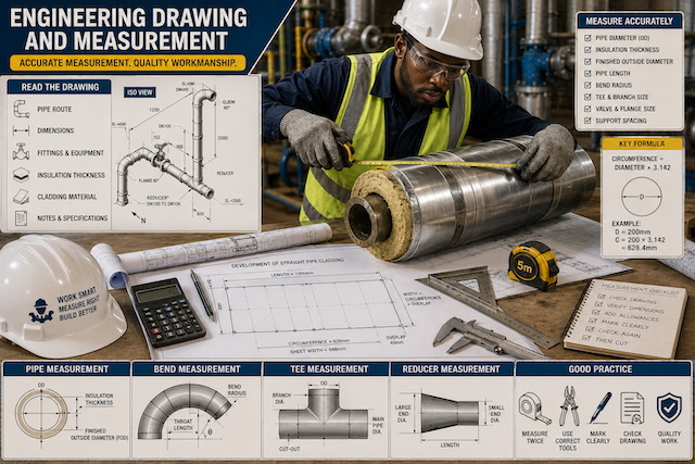
Introduction to Engineering Drawing and Measurement
Engineering drawing and measurement are essential skills in pipe insulation and tinsmith work. Drawings show what is to be insulated, fabricated, installed, or repaired. Measurement helps the worker transfer the information from the drawing to the actual pipe, insulation, or sheet metal.
A pipe insulator or tinsmith must be able to read simple drawings, identify pipe routes, understand dimensions, measure pipework accurately, and mark out materials before cutting. Poor measurement can lead to wasted insulation, poor cladding fit, open joints, water entry, poor finishing, and rework.
Good measurement and drawing interpretation support safe, accurate, and professional workmanship.
Basic Engineering Drawing
An engineering drawing is a technical document that uses lines, symbols, dimensions, views, and notes to communicate how an item should be made, installed, or maintained.
In pipe insulation and tinsmith work, drawings may show:
- Pipe routes
- Pipe sizes
- Pipe fittings
- Insulation thickness
- Cladding type
- Valves and flanges
- Pipe supports
- Equipment connections
- Installation areas
- Fabrication details
- Dimensions and levels
- Material specifications
Engineering drawings reduce guesswork. A worker should always check the drawing before cutting materials or starting installation.
Common Drawing Information
Most technical drawings contain important information that must be checked before work begins.
| Drawing Item | Purpose |
|---|---|
| Drawing title | Shows what the drawing is about |
| Drawing number | Identifies the drawing |
| Revision number | Shows the latest version |
| Scale | Shows the relationship between drawing size and real size |
| Notes | Provides instructions and special requirements |
| Dimensions | Shows sizes, lengths, heights, and distances |
| Symbols | Represents pipes, valves, fittings, supports, and equipment |
| Material specification | Shows required insulation, cladding, or accessories |
| Legend | Explains symbols and abbreviations |
| Approval status | Confirms whether the drawing is issued for construction or reference |
Never rely on an outdated drawing. If the drawing does not match the site condition, the issue should be reported before work continues.
Types of Drawings Used in Pipe Insulation Work
Pipe insulation and tinsmith work may involve several types of drawings.
| Drawing Type | Use |
|---|---|
| General arrangement drawing | Shows the overall layout of pipework and equipment |
| Piping layout drawing | Shows pipe routes, direction, fittings, and connections |
| Isometric drawing | Shows pipework in a 3D-like view with dimensions |
| Insulation specification | Shows insulation type, thickness, and finish |
| Cladding detail drawing | Shows how metal cladding should be formed and fixed |
| Fabrication drawing | Shows dimensions for making covers, elbows, reducers, or boxes |
| As-built drawing | Shows the final installed condition |
Each drawing type gives different information. The worker must know which drawing is needed for the task.
Reading Insulation Drawings
An insulation drawing shows the pipe or equipment to be insulated and may include insulation thickness, material type, cladding requirement, and special details.
Important items to check include:
- Pipe size
- Pipe length
- Pipe direction
- Number of bends, tees, reducers, valves, and flanges
- Insulation type
- Insulation thickness
- Cladding material
- Weatherproofing requirement
- Vapour barrier requirement
- Removable covers
- Pipe supports and hangers
- Access points for maintenance
A good worker reads the drawing first, checks the actual site, then measures before cutting.
Common Insulation Drawing Terms
| Term | Meaning |
|---|---|
| OD | Outside diameter |
| ID | Inside diameter |
| NB / NPS | Nominal pipe size |
| THK | Thickness |
| CL | Centre line |
| EL | Elevation |
| ISO | Isometric drawing |
| GA | General arrangement |
| TYP | Typical |
| SCH | Pipe schedule |
| C/W | Complete with |
| SS | Stainless steel |
| AL | Aluminium |
| GI | Galvanized iron / galvanized steel |
| V.B. | Vapour barrier |
| CUI | Corrosion under insulation |
Abbreviations may vary by company or project, so the drawing legend should always be checked.
Engineering Symbols
Drawings use symbols to represent items quickly. A learner should become familiar with common pipework and insulation symbols.
| Symbol / Item | Meaning |
|---|---|
| Straight line | Pipe run |
| Elbow / bend | Change in pipe direction |
| Tee | Branch connection |
| Reducer | Change in pipe size |
| Valve symbol | Flow control device |
| Flange | Bolted pipe connection |
| Support symbol | Pipe support or hanger |
| Insulation note | Required insulation type or thickness |
| Arrow | Direction of flow or installation direction |
| Break line | Section of pipe continues beyond drawing area |
Symbols should not be guessed. If a symbol is unclear, check the legend or ask for clarification.
Isometric Drawings
An isometric drawing shows pipework in a three-dimensional style. It helps workers understand pipe direction, height changes, offsets, and fittings more clearly than a flat plan drawing.
Isometric drawings are very useful in pipe insulation because pipe routes often move in different directions and levels.
An isometric drawing may show:
- Pipe length
- Pipe size
- Pipe direction
- Bends and elbows
- Tees and branches
- Reducers
- Valves and flanges
- Pipe supports
- Elevation changes
- Insulation specification
- Weld or joint locations
- North direction or reference orientation
Reading an Isometric Drawing
When reading an isometric drawing, first identify the pipe route from start to finish. Then check the pipe size, direction changes, fittings, and dimensions.
A practical method is to follow this order:
- Identify the line number or pipe reference.
- Confirm pipe size.
- Check the direction of flow.
- Trace the pipe route from one end to the other.
- Count elbows, tees, valves, flanges, and reducers.
- Check dimensions between fittings.
- Note elevation changes.
- Identify pipe supports and access points.
- Confirm insulation and cladding requirements.
- Compare the drawing with the actual site.
Isometric drawings help prevent mistakes when measuring elbows, offsets, and branch connections.
Pipe Measurements
Pipe measurement is the process of taking accurate dimensions from pipework before cutting insulation or cladding.
Important pipe measurements include:
| Measurement | Purpose |
|---|---|
| Pipe outside diameter | Helps select insulation size |
| Pipe circumference | Helps mark cladding width |
| Pipe length | Determines insulation and cladding length |
| Insulation thickness | Affects final cladding size |
| Finished outside diameter | Diameter after insulation is installed |
| Distance between fittings | Helps cut straight insulation sections |
| Bend radius | Helps fabricate elbow covers |
| Valve/flange size | Helps prepare removable boxes or covers |
| Support spacing | Helps plan insulation around supports |
| Offset distance | Helps fabricate offset cladding sections |
Accurate measurement is one of the biggest differences between rough work and professional work.
Measuring Pipe Diameter
Pipe diameter may be measured using a tape, caliper, pipe gauge, or by measuring circumference and calculating diameter.
For tinsmith and cladding work, workers often need the finished outside diameter after insulation is fitted. This includes the pipe diameter plus insulation thickness on both sides.
Example:
If pipe outside diameter is 100 mm and insulation thickness is 50 mm, then:
Finished outside diameter = 100 mm + 50 mm + 50 mm
Finished outside diameter = 200 mm
This finished size is important when making cladding.
Measuring Pipe Circumference
Circumference is the distance around the outside of a pipe or insulated pipe. It is needed when cutting sheet metal cladding to wrap around a pipe.
The basic formula is:
Circumference = Diameter × 3.142
Example:
If the finished outside diameter is 200 mm:
200 × 3.142 = 628.4 mm
Allowance must also be added for overlap, seam, or jointing method.
If the overlap is 40 mm, the sheet width should be:
628.4 mm + 40 mm = 668.4 mm
The worker may round this according to site practice and required accuracy.
Measuring Straight Pipe Sections
Straight pipe sections are usually measured between fittings, flanges, bends, supports, or equipment connections.
When measuring, consider:
- Where the insulation should start and stop
- Space around flanges and valves
- Cladding overlap
- Expansion or movement allowance
- Pipe supports and hangers
- Maintenance access
- Specification requirements
Do not assume all straight pipe sections are the same length. Always measure each section before cutting.
Measuring Elbows and Bends
Elbows and bends require more care than straight pipes because they are curved. Insulation and cladding must follow the bend neatly.
Measurements may include:
- Pipe diameter
- Insulation thickness
- Finished outside diameter
- Bend angle
- Bend radius
- Throat length
- Back length
- Number of segments required
- Overlap allowance
Elbow cladding is often made in segments, also called gores. The number of segments depends on the bend size, appearance requirement, and project standard.
Measuring Tees and Branches
A tee is a pipe fitting where one pipe branches from another. Tee insulation and cladding must fit tightly around the main pipe and the branch pipe.
Measurements may include:
- Main pipe diameter
- Branch pipe diameter
- Insulation thickness
- Main pipe cladding circumference
- Branch cladding circumference
- Centre point of branch
- Cut-out size
- Overlap and sealing allowance
Tee cut-outs should be marked accurately to avoid large gaps. Poor tee fitting can allow water entry and create poor appearance.
Measuring Valves and Flanges
Valves and flanges often require special covers or removable insulation boxes. These allow maintenance access without destroying the insulation system.
Measurements may include:
- Valve body length
- Valve height
- Flange diameter
- Bolt clearance
- Stem position
- Handwheel clearance
- Insulation thickness
- Cover length, width, and height
- Access requirements
- Removable fixing method
Do not cover valves or flanges in a way that prevents operation, inspection, or maintenance.
Layout and Development
Layout and development is the process of transferring measurements onto sheet metal or insulation material so it can be cut, folded, rolled, and fitted correctly.
In tinsmith work, layout and development are used to make:
- Straight pipe cladding
- Elbow covers
- Tee covers
- Reducer covers
- Offset covers
- Valve boxes
- Flange boxes
- End caps
- Weatherproof flashing
- Removable covers
A good layout must include all necessary allowances for overlap, seams, folds, rivets, screws, and finishing.
Marking Out Sheet Metal
Marking out is done before cutting. It must be accurate and clear.
Good marking-out practice includes:
- Place the sheet on a clean, flat surface.
- Confirm the correct material and thickness.
- Use a steel rule, tape, square, compass, divider, or template.
- Mark cut lines clearly.
- Mark bend lines separately from cut lines.
- Add overlap allowance.
- Add seam or lock allowance where required.
- Check measurements before cutting.
- Avoid unnecessary scratches on visible cladding surfaces.
- Mark parts to avoid confusion during assembly.
The rule is simple: measure carefully, mark clearly, check again, then cut.
Allowances in Layout Work
Allowances are extra measurements added for joining, overlapping, folding, or fitting.
Common allowances include:
| Allowance Type | Purpose |
|---|---|
| Overlap allowance | Allows one cladding edge to cover another |
| Seam allowance | Allows sheet metal edges to be joined |
| Fold allowance | Allows material for bending or hemming |
| Rivet allowance | Allows space for rivet fixing |
| Screw allowance | Allows proper screw spacing |
| Expansion allowance | Allows movement where required |
| Weather lap allowance | Helps prevent water entry outdoors |
If allowances are forgotten, the fabricated piece may be too small or difficult to fit.
Simple Development for Straight Pipe Cladding
For straight pipe cladding, the flat sheet size is based on the length of the pipe and the circumference of the insulated pipe.
Basic process:
- Measure the straight pipe length.
- Measure the finished outside diameter.
- Calculate or measure the circumference.
- Add overlap allowance.
- Mark length and width on sheet metal.
- Cut the sheet.
- Roll the sheet to the correct curve.
- Fit around insulation.
- Fasten and seal as required.
Example:
Pipe section length: 1,000 mm
Finished outside diameter: 200 mm
Circumference: 628 mm
Overlap allowance: 40 mm
Sheet size:
1,000 mm × 668 mm
This gives enough width to wrap around the insulated pipe with overlap.
Layout for Reducers
A reducer connects pipes of different sizes. Cladding for reducers is usually developed as a tapered shape.
Important measurements include:
- Large end diameter
- Small end diameter
- Reducer length
- Insulation thickness
- Finished large diameter
- Finished small diameter
- Overlap allowance
- Seam position
Reducer layouts require accurate marking because poor development can create gaps, wrinkles, or poor fit.
Layout for Offsets
An offset occurs when a pipe changes position while continuing in the same general direction. Offset cladding must follow the pipe movement and maintain a neat finish.
Important measurements include:
- Pipe diameter
- Insulation thickness
- Offset distance
- Angle of offset
- Length between bends
- Number of cladding sections
- Overlap direction
- Joint sealing requirement
Offsets should be measured carefully from the actual pipe, especially where drawings and site conditions differ.
Practical Measurement Checklist
Before cutting insulation or cladding, confirm:
| Check | Yes / No |
|---|---|
| Correct pipe or line has been identified | |
| Drawing revision is correct | |
| Pipe size is confirmed | |
| Insulation thickness is confirmed | |
| Material type is confirmed | |
| Straight length is measured | |
| Fittings are counted | |
| Valves and flanges are measured | |
| Finished outside diameter is calculated | |
| Overlap allowance is included | |
| Direction of cladding overlap is understood | |
| Weatherproofing requirement is clear | |
| Measurement has been checked twice |
This checklist helps reduce mistakes and material waste.
Real-Life Scenario
A tinsmith measures a bare pipe diameter and cuts aluminium cladding based only on that measurement. After the insulation is installed, the cladding is too small and cannot wrap around the insulated pipe.
The mistake happened because the worker measured only the pipe diameter and forgot to include the insulation thickness on both sides.
The correct approach is to measure or calculate the finished outside diameter after insulation, calculate the circumference, add overlap allowance, and then cut the cladding.
Common Drawing and Measurement Mistakes
Avoid these mistakes:
- Working from an old drawing revision.
- Ignoring drawing notes and specifications.
- Confusing pipe diameter with finished insulation diameter.
- Forgetting insulation thickness.
- Forgetting overlap allowance.
- Measuring only once before cutting.
- Using a damaged or unreadable tape measure.
- Cutting sheet metal before confirming the layout.
- Misreading isometric drawings.
- Ignoring valves, flanges, and supports.
- Assuming all elbows are the same size.
- Marking bend lines as cut lines.
- Forgetting weatherproofing requirements.
- Not checking site conditions against the drawing.
What a Pipe Insulator or Tinsmith Should Never Do
A pipe insulator or tinsmith should never:
- Cut material without measuring properly.
- Guess pipe size by appearance.
- Ignore drawing revisions.
- Fabricate cladding without overlap allowance.
- Cover valves or flanges without considering maintenance access.
- Use unclear markings on sheet metal.
- Change drawing requirements without approval.
- Ignore insulation thickness during cladding measurement.
- Leave large gaps around tees, bends, and reducers.
- Use poor measurement as an excuse for forcing materials into place.
Quick Recap
Engineering drawing and measurement help pipe insulators and tinsmiths work accurately and professionally. Drawings show pipe routes, sizes, fittings, insulation requirements, cladding details, and installation notes. Isometric drawings help workers understand pipe direction, bends, tees, reducers, and elevation changes. Accurate pipe measurement is necessary before cutting insulation or cladding. Layout and development transfer those measurements onto sheet metal or insulation materials. Good measurement reduces waste, improves fit, prevents water entry, and produces neat workmanship.