
Process Instruments
Introduction to Process Instruments
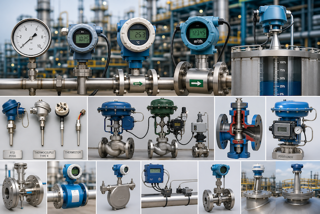
Process instruments are devices used to measure, display, transmit, control, or influence process conditions in an industrial system. They help operators and control systems understand what is happening in the plant and make safe, accurate decisions.
Common process instruments measure variables such as pressure, temperature, flow, and level. Other instruments, such as control valves, actuators, and positioners, help adjust the process based on signals from a controller.
A process instrument may be installed in the field, on a pipe, on a tank, in a control panel, or inside a process area. Field instruments such as pressure transmitters, flow meters, level sensors, thermometers, and analytical transmitters are widely used for process monitoring and control across industries.
Pressure Gauges
A pressure gauge is a local instrument used to show pressure visually. It usually has a dial and pointer, allowing operators and technicians to read pressure directly at the equipment or pipeline.
Pressure gauges are commonly used on:
- Pumps
- Compressors
- Filters
- Boilers
- Pressure vessels
- Hydraulic systems
- Pneumatic systems
- Process pipelines
- Water treatment systems
A pressure gauge is useful because it gives quick local indication without needing a control room display.
Common Types of Pressure Gauges
| Type | Common Use |
|---|---|
| Bourdon tube gauge | General industrial pressure measurement |
| Diaphragm gauge | Low pressure, corrosive fluids, or dirty service |
| Capsule gauge | Very low pressure measurement |
| Differential pressure gauge | Measures pressure difference between two points |
| Digital pressure gauge | Provides electronic pressure reading |
The Bourdon tube gauge is one of the most common types. Pressure causes the curved tube inside the gauge to move, and this movement drives the pointer on the dial.
Pressure Gauge Installation
Good pressure gauge installation improves accuracy, safety, and service life.
Important installation points include:
- Select the correct pressure range.
- Use the correct process connection.
- Install an isolation valve where required.
- Use a siphon on steam service to protect the gauge from high temperature.
- Use a snubber or dampener where pressure pulsation is present.
- Mount the gauge where it can be read safely.
- Avoid excessive vibration.
- Do not overtighten the gauge body.
- Ensure the gauge material is compatible with the process fluid.
- Check for leaks after installation.
A pressure gauge should not be installed where the process pressure can exceed its rating.
Pressure Transmitters
A pressure transmitter measures pressure and converts it into a standard signal, usually 4–20 mA, HART, or another digital communication signal. The signal is sent to a PLC, DCS, indicator, recorder, or controller.
Pressure transmitters are used when pressure needs to be monitored remotely or used for automatic control.
Common pressure transmitter applications include:
- Pump discharge pressure
- Tank pressure
- Vessel pressure
- Steam pressure
- Gas line pressure
- Filter differential pressure
- Flow measurement using differential pressure
- Level measurement using hydrostatic pressure
Emerson’s pressure transmitter documentation notes that transmitter location and impulse piping arrangement depend on the process, and it warns that process leaks and electrical shock can cause serious injury if installation and maintenance are not done correctly.
Types of Pressure Transmitters
| Type | Meaning | Common Use |
|---|---|---|
| Gauge pressure transmitter | Measures pressure relative to atmosphere | Pump lines, air systems, water systems |
| Absolute pressure transmitter | Measures pressure relative to vacuum | Vacuum systems, atmospheric correction, sealed processes |
| Differential pressure transmitter | Measures difference between two pressures | Flow, level, filter monitoring |
| Smart pressure transmitter | Provides digital setup, diagnostics, and communication | Modern process control systems |
Differential pressure transmitters are very important because they can be used not only for pressure difference, but also for flow and level applications.
Pressure Transmitter Installation
Good installation practice includes:
- Confirm instrument tag and range.
- Check process connection type.
- Mount transmitter securely.
- Use correct impulse tubing or manifold.
- Avoid blocked impulse lines.
- Keep high and low pressure sides correctly connected.
- Protect transmitter from vibration, heat, and flooding.
- Use correct cable glands and earthing.
- Confirm polarity for DC-powered transmitters.
- Check for leaks before returning to service.
- Calibrate and loop-check after installation.
Wrong impulse line connection can cause wrong readings. A differential pressure transmitter connected backwards may show negative or incorrect values.
Temperature Sensors
Temperature sensors measure the hotness or coldness of a process. They are used in tanks, pipes, vessels, furnaces, boilers, reactors, HVAC systems, food processing, power plants, and many industrial processes.
Common temperature sensors include:
- RTD
- Thermocouple
- Thermistor
A temperature sensor may connect directly to a temperature transmitter, controller, PLC input module, or local display.
RTD: Resistance Temperature Detector
An RTD measures temperature by using the change in electrical resistance of a metal element. The most common industrial RTD is the Pt100, which has a resistance of 100 ohms at 0°C.
RTDs are commonly used where good accuracy and stability are required.
| Feature | RTD |
|---|---|
| Signal principle | Resistance changes with temperature |
| Common type | Pt100 |
| Strength | Accurate and stable |
| Limitation | Usually not as suitable as thermocouples for very high temperatures |
| Common use | Process temperature, HVAC, water systems, precision measurement |
Thermocouple
A thermocouple is made from two different metals joined at one end. When the joined end is heated or cooled, it produces a small voltage related to temperature.
Thermocouples are widely used because they are rugged, affordable, and suitable for high-temperature applications. A thermocouple has a measuring junction and a reference junction, and it produces a voltage based on the temperature difference between them.
| Feature | Thermocouple |
|---|---|
| Signal principle | Small millivolt signal |
| Strength | Wide temperature range and rugged construction |
| Limitation | Usually less accurate than RTDs |
| Common use | Furnaces, boilers, engines, exhaust systems, high-temperature processes |
Common thermocouple types include Type K, J, T, E, N, R, S, and B. The correct type must match the process temperature and transmitter setting.
Thermistor
A thermistor is a temperature-sensitive resistor. Its resistance changes significantly with temperature.
Thermistors are very sensitive over a smaller temperature range. They are common in electronics, HVAC equipment, battery systems, small machines, and temperature protection circuits.
| Feature | Thermistor |
|---|---|
| Signal principle | Resistance changes strongly with temperature |
| Strength | Very sensitive |
| Limitation | Limited temperature range compared with thermocouples |
| Common use | HVAC, electronic equipment, protection circuits |
RTD vs Thermocouple vs Thermistor
| Feature | RTD | Thermocouple | Thermistor |
|---|---|---|---|
| Output | Resistance | Millivoltage | Resistance |
| Accuracy | High | Moderate | High over limited range |
| Temperature range | Medium to high | Very wide | Usually limited |
| Stability | Good | Moderate | Good within range |
| Cost | Higher than many thermocouples | Often low | Usually low to moderate |
| Common use | Accurate process measurement | High-temperature industrial service | HVAC and electronic sensing |
RTDs, thermocouples, and thermistors differ in accuracy, temperature range, cost, ruggedness, and application suitability, so the correct sensor should be selected based on the process requirement.
Temperature Transmitters
A temperature transmitter receives a signal from a temperature sensor and converts it into a standard signal such as 4–20 mA or a digital communication signal.
Temperature transmitters may be:
- Head-mounted
- Field-mounted
- DIN-rail mounted
- Integrated into a temperature assembly
A transmitter improves signal transmission because raw RTD resistance or thermocouple millivoltage can be affected by cable length, noise, connection errors, and environment.
Thermowells
A thermowell is a protective tube installed into a pipe or vessel to protect the temperature sensor from pressure, flow, corrosion, and mechanical damage.
Thermowells allow sensors to be removed for maintenance without opening the process, if isolation and design permit.
Good thermowell practice includes:
- Use the correct material.
- Confirm insertion length.
- Avoid excessive vibration.
- Ensure process compatibility.
- Install correctly with suitable sealing.
- Confirm sensor contact inside the thermowell.
- Do not force a sensor into a blocked or damaged thermowell.
Flow Meters
A flow meter measures the rate of movement of liquid, gas, steam, or slurry through a pipe or channel. Flow measurement is important for production control, batching, custody transfer, chemical dosing, pump monitoring, utility measurement, and energy management.
Endress+Hauser describes flow measurement as supporting process control, from single measuring points to complete higher-level control system solutions.
Common Types of Flow Meters
| Flow Meter Type | Working Principle | Common Use |
|---|---|---|
| Differential pressure flow meter | Measures pressure drop across a restriction | Steam, gas, liquid flow |
| Magnetic flow meter | Measures conductive liquid flow using electromagnetic induction | Water, wastewater, chemicals |
| Coriolis flow meter | Measures mass flow using tube vibration | Accurate liquid and gas measurement |
| Ultrasonic flow meter | Uses sound waves to measure flow velocity | Water, gas, clamp-on measurement |
| Vortex flow meter | Measures vortices shed by a bluff body | Steam, gas, liquids |
| Turbine flow meter | Uses rotating blades in the flow stream | Clean liquids and gases |
| Rotameter | Uses a floating element in a tapered tube | Local flow indication |
| Thermal mass flow meter | Uses heat transfer to measure gas flow | Compressed air and gas systems |
Major flow-measurement principles include Coriolis, electromagnetic, ultrasonic, vortex, thermal mass, and differential pressure methods.
Differential Pressure Flow Measurement
Differential pressure flow measurement uses a restriction in the pipe, such as an orifice plate, venturi, or flow nozzle. As fluid passes through the restriction, pressure drops. The differential pressure transmitter measures this pressure difference and the system calculates flow.
Common components include:
- Orifice plate or primary element
- Flange taps or pressure taps
- Impulse lines
- Manifold
- Differential pressure transmitter
- Flow computer or control system
Good installation requires correct impulse line connection, proper orientation, leak-free fittings, and correct transmitter range.
Magnetic Flow Meter
A magnetic flow meter measures conductive liquid flow. It has no obstruction inside the pipe, so it is useful for water, wastewater, slurry, and some chemical applications.
Magnetic flow meters require:
- Conductive liquid
- Full pipe condition
- Correct grounding
- Proper pipe installation
- Suitable liner and electrode material
A magnetic flow meter will not work properly on non-conductive fluids such as oil, gas, or steam.
Coriolis Flow Meter
A Coriolis flow meter measures mass flow directly. It can also provide density and temperature information in many designs.
It is used where high accuracy is needed, such as chemical dosing, custody transfer, batching, and critical process measurement.
Coriolis meters are usually more expensive but provide strong measurement performance.
Ultrasonic Flow Meter
An ultrasonic flow meter uses sound waves to measure flow velocity. Some types are installed inline, while clamp-on types can be attached outside the pipe.
Ultrasonic flow meters are useful where pipe cutting is difficult or where non-intrusive measurement is required.
Good performance depends on:
- Correct pipe size entry
- Proper sensor spacing
- Good acoustic contact
- Correct pipe material
- Enough straight pipe run
- Proper fluid condition
Vortex Flow Meter
A vortex flow meter measures vortices created when fluid passes a bluff body inside the meter. The frequency of the vortices is related to flow velocity.
Vortex meters are commonly used for steam, gas, and liquid applications.
They require good installation conditions and are not ideal for very low flows or heavy vibration areas.
Level Transmitters
A level transmitter measures the height or quantity of material inside a tank, vessel, sump, silo, or container. It may measure liquid level, solid level, interface level, or point level.
Level measurement helps prevent overflow, dry running, incorrect batching, pump damage, poor inventory control, and unsafe operation.
Common Types of Level Instruments
| Level Instrument | Common Use |
|---|---|
| Sight glass | Local visual indication |
| Float switch | Point level detection |
| Displacer transmitter | Liquid level or interface measurement |
| Differential pressure level transmitter | Hydrostatic tank level measurement |
| Radar level transmitter | Non-contact continuous level measurement |
| Ultrasonic level transmitter | Non-contact level measurement using sound |
| Capacitance level transmitter | Level measurement using capacitance change |
| Guided wave radar | Level measurement along a probe |
| Vibrating fork switch | Point level detection |
Differential Pressure Level Measurement
Differential pressure level measurement uses the pressure created by the height of liquid in a tank. The transmitter converts hydrostatic pressure into level.
This method depends on:
- Liquid density
- Tank pressure condition
- Correct high and low side connection
- Proper impulse line or capillary installation
- Correct transmitter range
It is often used on pressurised vessels, open tanks, and interface applications.
Radar Level Transmitter
Radar level transmitters use microwave signals to measure the distance from the transmitter to the material surface. They are widely used for liquids, solids, and difficult process conditions.
Radar is useful because it is non-contact and can work in many conditions where pressure, vapour, or temperature may affect other technologies.
Ultrasonic Level Transmitter
An ultrasonic level transmitter sends sound pulses toward the material surface and measures the time it takes for the echo to return.
It is commonly used in water tanks, sumps, wastewater, and general storage applications.
Performance can be affected by foam, vapour, turbulence, temperature changes, dust, and obstructions.
Control Valves
A control valve is a final control element used to regulate the flow of liquid, gas, or steam in a process. It receives a signal from a controller and changes the valve opening to adjust the process.
Control valves are used for:
- Flow control
- Pressure control
- Temperature control
- Level control
- Mixing control
- Steam control
- Cooling water control
- Chemical dosing
A control valve is one of the most important final control elements in process control.
Main Parts of a Control Valve
| Part | Function |
|---|---|
| Valve body | Contains the flow path |
| Trim | Controls flow inside the valve |
| Plug / ball / disc | Opens, closes, or restricts flow |
| Seat | Sealing surface inside the valve |
| Stem | Transfers movement from actuator to plug |
| Actuator | Moves the valve stem or shaft |
| Positioner | Controls valve position accurately |
| Packing | Seals around the stem |
| Bonnet | Supports stem and packing area |
Common Control Valve Types
| Valve Type | Common Use |
|---|---|
| Globe control valve | Accurate modulating control |
| Ball valve | On/off or some control applications |
| Butterfly valve | Large flow, low-pressure drop applications |
| Diaphragm valve | Corrosive or sanitary applications |
| Eccentric rotary valve | Slurry or difficult service |
| Angle valve | High-pressure drop or special flow direction |
The correct valve type depends on the fluid, pressure, temperature, flow requirement, shutoff need, and control performance.
Actuators
An actuator provides the force or motion needed to move a valve. It receives pneumatic, electric, or hydraulic energy and converts it into mechanical movement.
Common actuator types include:
| Actuator Type | Description |
|---|---|
| Pneumatic actuator | Uses compressed air |
| Electric actuator | Uses an electric motor |
| Hydraulic actuator | Uses pressurised hydraulic fluid |
| Spring-return actuator | Uses spring force to move valve to fail-safe position |
| Double-acting actuator | Requires power to move in both directions |
Pneumatic actuators are common in process industries because they are simple, fast, and suitable for many hazardous areas when designed properly.
Positioners
A valve positioner compares the desired valve position with the actual valve position and adjusts actuator pressure or control signal to move the valve correctly.
Positioners improve valve accuracy, response, and stability.
A positioner may receive:
- 4–20 mA signal
- Pneumatic signal
- Digital signal
- HART or other communication
A smart valve positioner may also provide diagnostics, travel feedback, calibration support, and fault information.
Control Valve Fail Position
Control valves are often designed to move to a safe position if air supply, power, or signal is lost.
Common fail positions include:
| Fail Position | Meaning |
|---|---|
| Fail open | Valve opens when control energy is lost |
| Fail closed | Valve closes when control energy is lost |
| Fail last | Valve stays in last position where designed |
The correct fail position depends on process safety. For example, a fuel gas valve may fail closed, while a cooling water valve may fail open depending on the process design.
Instrument Installation Good Practice
Good installation is essential for instrument performance. Even a high-quality instrument can give poor readings if installed wrongly.
Good practice includes:
- Confirm instrument tag before installation.
- Check datasheet and range.
- Use correct process connection.
- Install in the correct orientation.
- Protect instruments from excessive heat and vibration.
- Use suitable cable glands and seals.
- Ensure proper earthing and shielding.
- Avoid water entry into instrument housings.
- Follow manufacturer instructions.
- Check calibration before commissioning.
- Perform loop check after wiring.
- Document all work.
Instrument identification and documentation are important. ISA-5.1 provides a uniform method for instrument symbols and identification so people reading flow diagrams can understand measurement and control functions.
Instrument Maintenance
Process instruments require maintenance to remain accurate and reliable.
Common maintenance activities include:
- Visual inspection
- Cleaning
- Checking for leaks
- Checking cable glands and terminals
- Checking impulse lines
- Calibration
- Loop checking
- Functional testing
- Replacing damaged parts
- Checking transmitter configuration
- Checking valve travel
- Checking actuator air supply
- Reviewing error codes and diagnostics
Maintenance should be documented. A fault that is not recorded may repeat without being properly investigated.
Common Process Instrument Faults
| Fault | Possible Cause |
|---|---|
| No pressure reading | Blocked impulse line, failed transmitter, no power |
| Gauge reading unstable | Vibration, pulsation, damaged gauge |
| Temperature reading high or low | Wrong sensor type, poor sensor contact, bad wiring |
| Flow reading zero | No flow, empty pipe, wiring fault, failed meter |
| Flow reading unstable | Air bubbles, turbulence, poor grounding, vibration |
| Level reading wrong | Wrong density, foam, buildup, blocked impulse line |
| Control valve not moving | No air supply, failed actuator, bad positioner, stuck stem |
| Valve hunting | Poor tuning, positioner problem, sticking valve |
| Signal fixed at 4 mA | Process at low range, wiring issue, transmitter fault |
| Signal above 20 mA | Overrange process, transmitter fault, configuration issue |
Troubleshooting should follow a logical process. Check power, signal, process connection, configuration, calibration, and mechanical condition before replacing instruments.
Real-Life Scenario
A flow reading in the control room suddenly drops to zero, and the operator assumes the flow meter has failed. The technician checks the instrument and finds that the transmitter has power and the signal cable is intact. Further inspection shows that the pipe is partially empty because a pump upstream has stopped.
The instrument was not the problem. The process condition changed.
A good instrumentation technician does not replace instruments blindly. The technician checks the process condition, power supply, wiring, configuration, and instrument health before concluding that the instrument is faulty.
Common Beginner Mistakes
Avoid these mistakes:
- Installing instruments without checking tag numbers.
- Mixing up high and low sides of a differential pressure transmitter.
- Selecting the wrong temperature sensor type.
- Ignoring thermowell condition.
- Installing flow meters without required straight pipe run.
- Using magnetic flow meters on non-conductive fluids.
- Ignoring empty pipe conditions.
- Blocking valve operation with poor installation.
- Confusing actuator fault with valve body fault.
- Ignoring air supply to pneumatic actuators.
- Leaving instrument covers loose after work.
- Replacing instruments without checking wiring and power.
- Failing to document calibration and maintenance.
What an Instrumentation Technician Should Never Do
An instrumentation technician should never:
- Remove an instrument from process service without isolation.
- Loosen pressure transmitter flanges while in service.
- Work on pressurised impulse lines without proper isolation.
- Change instrument range without approval.
- Install a sensor without checking compatibility.
- Ignore process temperature, pressure, or chemical hazards.
- Bypass a control valve or positioner without authorisation.
- Leave instrument cable entries open.
- Ignore hazardous-area requirements.
- Hand over an instrument without calibration or loop checking where required.
- Hide abnormal readings or failed tests.
Quick Recap
Process instruments measure and control important process variables such as pressure, temperature, flow, and level. Pressure gauges provide local indication, while pressure transmitters send signals to control systems. Temperature sensors include RTDs, thermocouples, and thermistors. Flow meters use different principles such as differential pressure, magnetic, Coriolis, ultrasonic, vortex, turbine, and thermal mass measurement. Level transmitters measure liquid or solid levels using methods such as differential pressure, radar, ultrasonic, float, or capacitance. Control valves, actuators, and positioners adjust the process based on control signals. Good performance depends on correct selection, installation, calibration, maintenance, documentation, and safe work practices.