
Testing and Commissioning
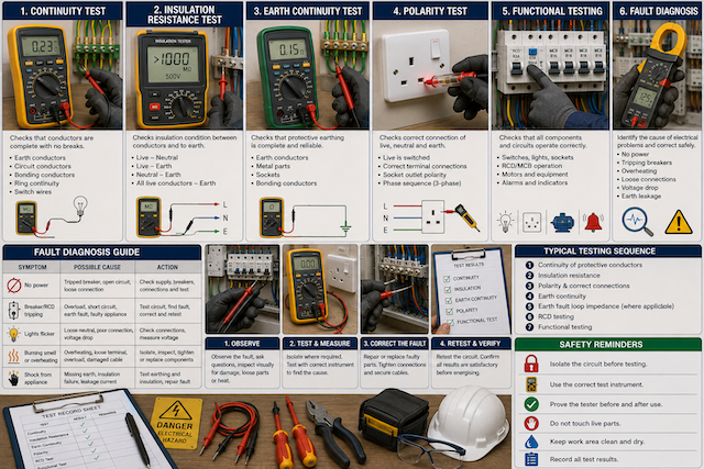
Introduction to Testing and Commissioning
Testing and commissioning are the final safety checks carried out before an electrical installation is put into use. Testing confirms that the wiring, protection, earthing, polarity, insulation, and connected equipment are safe and suitable. Commissioning confirms that the installation works correctly under normal operating conditions.
Testing should not be treated as a formality. A circuit may look neat and still be unsafe if there is poor insulation, wrong polarity, missing earth continuity, loose connections, or a hidden wiring fault. HSE guidance highlights the need for suitable electrical test equipment and safe testing practices when working on electrical systems.
Safe Testing Procedure
Before any test is carried out, the worker must understand the circuit, choose the correct instrument, and follow safe isolation procedures.
Basic safe testing rules include:
- Use the correct test instrument for the task.
- Inspect test leads and probes before use.
- Confirm the instrument rating is suitable.
- Isolate circuits before dead testing.
- Prove the tester before and after use.
- Keep fingers behind probe guards.
- Do not touch exposed conductors.
- Record test results clearly.
- Do not energise a circuit until it is confirmed safe.
- Report and correct unsafe readings before commissioning.
Electrical testing is normally carried out in a logical order. Dead tests such as continuity, insulation resistance, and polarity are completed before live tests and functional checks. Several industry guides based on BS 7671 describe this sequence as continuity of protective conductors, insulation resistance, polarity, earth fault loop impedance, RCD performance, and functional testing.
Continuity Test
A continuity test checks whether an electrical path is complete. It confirms that conductors are properly connected from one end of the circuit to the other.
Continuity testing is used to check:
| Area | Purpose |
|---|---|
| Protective conductors | Confirms earth path is complete |
| Circuit conductors | Confirms no break in the conductor |
| Ring circuits | Confirms ring continuity |
| Switch wires | Confirms correct connection path |
| Bonding conductors | Confirms bonding is continuous |
| Cable cores | Identifies open circuits or broken conductors |
A continuity test is usually carried out with the circuit isolated. The test instrument sends a small current through the conductor and measures whether the path is complete.
Why Continuity Testing Is Important
A broken conductor can stop a circuit from working. A broken protective conductor is more dangerous because exposed metal parts may not be safely earthed during a fault.
Continuity testing helps identify:
- Broken wires
- Loose connections
- Disconnected earth conductors
- Incorrect terminations
- Faulty switches
- Damaged cables
- Incomplete ring circuits
A circuit should not be energised if continuity of the protective conductor is not confirmed.
Basic Continuity Test Process
A basic continuity test may involve:
- Isolating the circuit.
- Confirming the circuit is dead.
- Setting the meter to continuity or low resistance.
- Connecting the test leads to both ends of the conductor.
- Checking for a low resistance reading or audible continuity signal.
- Recording the result.
- Investigating any open circuit or high resistance reading.
A low resistance reading usually indicates a complete path. A very high reading or no reading may indicate a break, loose connection, or wrong test point.
Insulation Resistance Test
An insulation resistance test checks the condition of cable and equipment insulation. It confirms that conductors are properly separated from each other and from earth.
Insulation resistance testing helps detect:
- Damaged insulation
- Moisture inside cables or accessories
- Cable deterioration
- Short circuits
- Leakage paths
- Contamination
- Crushed or overheated cables
This test is important because poor insulation can lead to electric shock, tripping, overheating, fire, or equipment failure.
How Insulation Resistance Testing Works
An insulation resistance tester applies a DC test voltage between conductors and measures how much resistance exists through the insulation.
Common test points include:
| Test Between | Purpose |
|---|---|
| Live and neutral | Checks insulation between active conductors |
| Live and earth | Checks leakage from live to earth |
| Neutral and earth | Checks unwanted connection or leakage |
| All live conductors and earth | Checks overall insulation condition |
The circuit must be isolated before testing. Sensitive electronic equipment, lamps, dimmers, surge protection devices, and certain appliances may need to be disconnected before the test to avoid damage.
Insulation Resistance Safety
During insulation resistance testing:
- Ensure the circuit is isolated.
- Confirm no person is touching the circuit.
- Disconnect sensitive equipment where required.
- Use the correct test voltage.
- Do not touch conductors during the test.
- Discharge the circuit after testing.
- Investigate low readings before energising.
A low insulation resistance reading should not be ignored. It may indicate moisture, damaged cable, poor accessory condition, or a wiring fault.
Earth Continuity Test
An earth continuity test checks that the protective earthing conductor is continuous and properly connected.
Earthing is one of the most important safety systems in an electrical installation. If a fault makes exposed metal parts live, the earth conductor provides a path for fault current so the protective device can operate quickly.
Electrical Safety First explains that earthing helps fault current flow through the protective conductor so a fuse, circuit breaker, or RCD can disconnect the supply.
What Earth Continuity Testing Checks
Earth continuity testing confirms that:
- Earth conductors are connected.
- Metal accessories are bonded where required.
- Consumer unit earth bar is properly connected.
- Socket earth terminals are continuous.
- Metal light fittings are earthed.
- Bonding conductors are intact.
- Exposed conductive parts have a fault path.
Without earth continuity, an installation may appear to work but still be dangerous.
Basic Earth Continuity Test Process
A basic earth continuity test may involve:
- Isolating the circuit.
- Confirming absence of voltage.
- Connecting one test lead to the main earth terminal or earth bar.
- Connecting the other test lead to the earth point being tested.
- Measuring resistance.
- Confirming the reading is acceptable.
- Recording the result.
- Correcting any high resistance or open-circuit result.
A high resistance reading may be caused by loose terminals, corrosion, damaged conductors, poor bonding, or incorrect connections.
Polarity Test
A polarity test confirms that live, neutral, and earth conductors are connected to the correct terminals.
Correct polarity is essential because switches, fuses, breakers, sockets, and protective devices must operate on the correct conductor.
Polarity testing helps confirm that:
| Item | What Should Be Correct |
|---|---|
| Switches | Live conductor is switched |
| Socket outlets | Live, neutral, and earth are correctly positioned |
| Distribution boards | Incoming and outgoing conductors are correctly connected |
| Light fittings | Live and neutral are correctly connected |
| Protective devices | Live conductor is protected and controlled |
| Three-phase circuits | Phase sequence is correct where required |
Why Polarity Matters
Wrong polarity can create dangerous conditions. A light may be switched off but still have live parts inside the fitting. A socket may power an appliance but still be wired dangerously. A protective device may not disconnect the correct conductor.
Polarity testing should be completed before the installation is put into service.
Basic Polarity Test Process
A polarity test may involve:
- Checking wiring visually before energising.
- Carrying out dead polarity testing where possible.
- Confirming switches are connected in the live conductor.
- Checking socket terminals for live, neutral, and earth.
- Verifying distribution board connections.
- Testing live circuits only when safe and authorised.
- Recording the result.
For three-phase systems, phase sequence testing may also be required to ensure motors rotate in the correct direction.
Functional Testing
Functional testing confirms that the installation and connected equipment operate correctly after safety tests have been completed.
Functional testing may include:
| Item | What to Check |
|---|---|
| Switches | Operate correctly |
| Lights | Turn on and off correctly |
| Socket outlets | Provide correct supply |
| RCDs / RCCBs | Trip when tested |
| MCBs / breakers | Correct operation and identification |
| Isolators | Disconnect supply properly |
| Emergency stops | Stop equipment correctly |
| Motors | Start, stop, and rotate correctly |
| Control panels | Indicators, relays, timers, and controls function properly |
| Alarms | Activate correctly |
| Fans and pumps | Run safely and in correct direction |
Functional testing is not a replacement for electrical safety testing. It comes after safety checks have confirmed that the circuit is safe to energise.
RCD Functional Test
Where an RCD or RCCB is installed, its test button should be operated to confirm the device trips mechanically. Instrument testing may also be required to confirm trip time and performance according to the applicable standard.
A test button confirms basic operation, but it does not fully prove that the RCD will trip within the required time under all fault conditions.
Fault Diagnosis
Fault diagnosis is the process of identifying the cause of an electrical problem. It requires observation, testing, logical thinking, and safe working methods.
Electrical faults should be approached carefully. Guesswork can make faults worse or create unsafe conditions.
Common Electrical Faults
| Fault | Possible Cause |
|---|---|
| Circuit not working | Open circuit, tripped breaker, loose connection |
| Breaker keeps tripping | Overload, short circuit, earth fault, faulty appliance |
| RCD trips | Leakage current, moisture, faulty equipment, insulation failure |
| Socket has no power | Loose terminal, damaged cable, faulty breaker |
| Light flickers | Loose connection, faulty lamp, poor switch contact |
| Burning smell | Overheating, loose terminal, overloaded circuit |
| Low voltage | Voltage drop, supply issue, overloaded circuit |
| Shock from appliance | Poor earthing, insulation failure, leakage current |
| Motor runs wrong direction | Incorrect phase sequence |
| Motor trips on start | Overload, mechanical jam, phase loss, starter fault |
Basic Fault Diagnosis Process
A safe fault diagnosis process should follow a clear method:
- Understand the complaint.
- Ask what happened before the fault appeared.
- Check the circuit drawing or layout.
- Inspect visually for damage, heat, smell, loose parts, or water.
- Isolate the circuit where required.
- Test safely using the correct instrument.
- Identify whether the fault is open circuit, short circuit, earth fault, overload, or equipment failure.
- Correct the fault.
- Retest the circuit.
- Confirm safe operation.
- Record the repair where required.
Never keep resetting a tripped breaker or RCD without finding the cause.
Commissioning
Commissioning is the process of confirming that a completed installation is safe, functional, and ready for use.
Commissioning may include:
- Final inspection
- Verification of test results
- Functional testing
- Labelling of circuits
- Checking protective devices
- Confirming earthing and bonding
- Checking load operation
- Handing over documentation
- Explaining basic operation to the user
- Recording defects or limitations
Commissioning should only be completed when the installation has passed the required checks and is safe to energise.
Test Records and Documentation
Test results should be recorded clearly. Good documentation helps future maintenance, inspection, fault diagnosis, and compliance.
Records may include:
- Circuit details
- Cable sizes
- Protective device ratings
- Continuity results
- Insulation resistance results
- Polarity results
- Earth continuity results
- RCD test results
- Functional test results
- Faults found and corrected
- Date of test
- Name of person carrying out the test
Poor documentation makes future maintenance harder and may create safety risks.
Real-Life Scenario
A newly installed socket circuit appears to work when a phone charger is plugged in. However, during testing, the earth continuity reading is open circuit.
The socket must not be put into service.
Even though the socket supplies power, the protective earth path is missing. If a connected appliance develops a fault, exposed metal parts may become live and create a shock risk. The correct action is to isolate the circuit, trace the earth conductor fault, correct the connection, retest earth continuity, confirm polarity, and only energise the circuit when the test results are safe.
Common Mistakes in Testing and Commissioning
Avoid these unsafe practices:
- Energising circuits before completing dead tests.
- Assuming a circuit is safe because it works.
- Using damaged test leads.
- Testing with the wrong meter setting.
- Failing to prove the tester before and after use.
- Ignoring low insulation resistance.
- Ignoring missing earth continuity.
- Not checking polarity.
- Resetting breakers repeatedly without fault diagnosis.
- Failing to disconnect sensitive equipment before insulation testing.
- Not recording test results.
- Treating functional testing as the same as safety testing.
- Allowing unqualified persons to test live circuits.
What an Electrical Worker Should Never Do
An electrical worker should never:
- Test a circuit without understanding the test method.
- Touch conductors during insulation resistance testing.
- Energise a circuit with poor insulation.
- Energise a circuit with missing earth continuity.
- Ignore reversed polarity.
- Use a faulty or unsuitable test instrument.
- Use bare hands to check for voltage.
- Skip testing because the installation “looks correct.”
- Leave faults undocumented.
- Guess the cause of repeated tripping.
- Work live without authorisation, competence, and suitable controls.
- Hand over an installation that has not been tested and commissioned.
Quick Recap
Testing and commissioning confirm that an electrical installation is safe and ready for use. Continuity testing checks that conductors are complete. Insulation resistance testing checks the condition of insulation. Earth continuity testing confirms the protective earth path. Polarity testing confirms correct live, neutral, and earth connections. Functional testing confirms that switches, sockets, protective devices, motors, and controls operate correctly. Fault diagnosis must be done safely and logically, with proper testing, correction, retesting, and documentation.