
Instrument Calibration
Introduction to Instrument Calibration
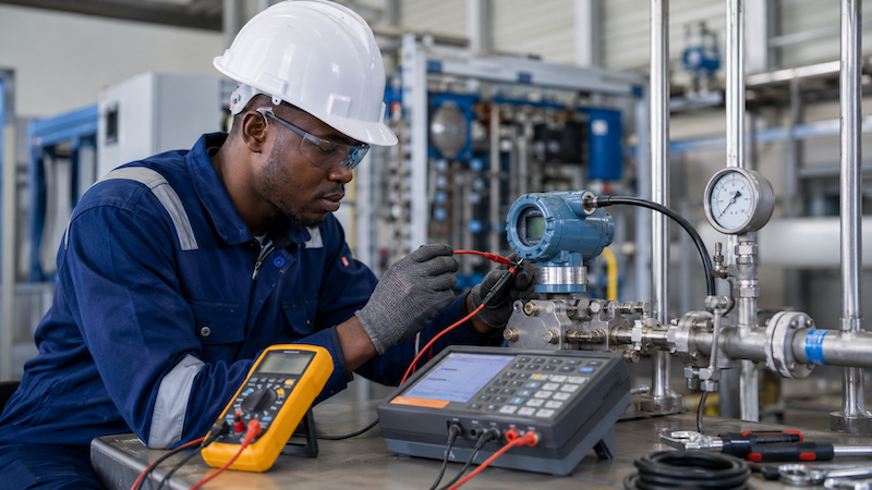
Instrument calibration is the process of comparing an instrument’s reading with a known reference standard to confirm whether the instrument is measuring correctly. Where necessary, the instrument may be adjusted, repaired, or documented for further action.
Calibration is important because instruments can drift over time due to vibration, heat, pressure, ageing, contamination, moisture, electrical faults, incorrect handling, or harsh process conditions. A transmitter, gauge, sensor, or control valve may still appear to work but may no longer be giving accurate results.
ISA describes calibration as comparing measuring equipment against a standard instrument of higher accuracy to detect, adjust, correct, and document the accuracy of the instrument being checked.
Why Calibration Matters
Calibration helps ensure that process measurements are reliable. Reliable measurements support safe operation, product quality, process efficiency, maintenance planning, and regulatory compliance.
Calibration helps to:
- Confirm instrument accuracy.
- Detect zero error, span error, drift, and linearity problems.
- Improve process control and stability.
- Prevent wrong operator decisions.
- Reduce safety risks.
- Support quality assurance.
- Provide maintenance and audit records.
- Confirm that readings are within acceptable tolerance.
- Improve confidence in control-room displays and alarms.
A poorly calibrated instrument can make a safe process look unsafe or make an unsafe process look normal.
Calibration Principles
Calibration is based on comparison. A known input is applied to the instrument, and the instrument output is checked against the expected value.
For example, if a pressure transmitter is ranged from 0 to 10 bar, the technician may apply known pressures at 0%, 25%, 50%, 75%, and 100% of range, then check whether the output matches the expected signal.
For a 4–20 mA transmitter:
| Input Percentage | Expected Output |
|---|---|
| 0% | 4 mA |
| 25% | 8 mA |
| 50% | 12 mA |
| 75% | 16 mA |
| 100% | 20 mA |
If the output is outside the allowed tolerance, adjustment or repair may be required.
Calibration, Adjustment and Verification
Calibration, adjustment, and verification are related, but they are not exactly the same.
| Term | Meaning |
|---|---|
| Calibration | Comparing an instrument with a known standard and recording the error |
| Adjustment | Changing the instrument setting to reduce error |
| Verification | Confirming that the instrument meets the required tolerance |
| As-found check | Condition of the instrument before adjustment |
| As-left check | Condition of the instrument after adjustment or repair |
A technician should not adjust an instrument immediately without first recording the as-found condition. The as-found result shows how the instrument was performing before any correction.
Calibration Procedures
A calibration procedure is a step-by-step method for checking an instrument safely and accurately. It should follow the manufacturer’s manual, company procedure, project specification, and safety requirements.
A general calibration procedure includes:
- Identify the instrument tag.
- Confirm the instrument type and service.
- Review datasheet and calibration range.
- Confirm the required tolerance.
- Obtain permit and isolation where required.
- Use a calibrated reference standard.
- Inspect the instrument and test equipment.
- Connect the test equipment correctly.
- Perform as-found test.
- Adjust zero and span if required and authorised.
- Perform as-left test.
- Record all readings clearly.
- Restore the instrument to service.
- Complete the calibration certificate or report.
Process calibration tools such as loop calibrators are commonly used for 4–20 mA loop checks and transmitter troubleshooting.
Safe Calibration Practice
Calibration may involve electrical signals, pressurised systems, temperature sources, process fluids, chemicals, hot surfaces, or live control loops. Safety must come first.
Safe calibration practice includes:
- Wear required PPE.
- Confirm the instrument tag before starting.
- Understand the process connected to the instrument.
- Obtain permit to work where required.
- Isolate and depressurise process connections before removal.
- Use Lockout/Tagout where required.
- Confirm electrical isolation before wiring changes.
- Do not open impulse lines under pressure.
- Use the correct test leads, hoses, fittings, and adapters.
- Do not exceed the instrument range or calibrator range.
- Return valves, manifolds, and bypasses to correct position after work.
- Inform operations before removing or simulating signals.
- Record all test results.
Never treat calibration as only an electrical activity. Many instruments are connected to pressure, temperature, level, flow, chemicals, steam, gas, or hazardous process conditions.
Calibration Equipment
Calibration equipment is used to generate, measure, or simulate known values. The reference equipment must be more accurate than the instrument being checked and should have valid calibration status.
Common calibration equipment includes:
| Equipment | Common Use |
|---|---|
| Loop calibrator | Sourcing and measuring 4–20 mA signals |
| Multimeter | Measuring voltage, current, resistance, and continuity |
| Pressure calibrator | Checking pressure gauges and pressure transmitters |
| Hand pressure pump | Generating pneumatic or hydraulic pressure |
| Deadweight tester | High-accuracy pressure calibration |
| Dry block calibrator | Checking temperature sensors and transmitters |
| Temperature bath | Accurate temperature calibration |
| Decade box | Simulating resistance for RTD circuits |
| Thermocouple simulator | Simulating thermocouple signals |
| HART communicator | Configuring and checking smart transmitters |
| Portable documenting calibrator | Recording as-found and as-left results |
| Test gauge | Pressure comparison in field checks |
Reference standards used for calibration should themselves be calibrated and traceable to recognised standards.
Traceability
Traceability means that a measurement result can be linked to a recognised reference through a documented unbroken chain of calibrations, with each step contributing to measurement uncertainty. NIST uses and recommends this definition of metrological traceability.
In practical terms, this means the calibrator used to check a transmitter should have its own valid calibration certificate. That certificate should link back to a higher-level reference standard.
Traceability helps ensure that measurements are trusted, repeatable, and acceptable for quality and safety purposes.
Calibration Range and Test Points
Before calibration, the technician must confirm the instrument range.
Example:
Pressure transmitter range: 0 to 10 bar
| Percentage | Input Pressure | Expected Output |
|---|---|---|
| 0% | 0 bar | 4 mA |
| 25% | 2.5 bar | 8 mA |
| 50% | 5 bar | 12 mA |
| 75% | 7.5 bar | 16 mA |
| 100% | 10 bar | 20 mA |
Common calibration checks may use three points or five points. Five-point calibration gives a better picture of the instrument’s response across the range.
Zero and Span Adjustment
Zero and span are two important calibration settings.
| Term | Meaning |
|---|---|
| Zero | The output at the lower range value |
| Span | The difference between upper range value and lower range value |
| Zero adjustment | Corrects the reading at the low end of range |
| Span adjustment | Corrects the reading at the high end of range |
For a 4–20 mA transmitter:
- Zero output = 4 mA
- Span output = 16 mA
- Full-scale output = 20 mA
Zero defines the start of the range, while span defines the full scale of the measurement. Structured zero and span adjustment is important for reliable transmitter calibration.
Zero Adjustment Example
A pressure transmitter is ranged from 0 to 10 bar.
At 0 bar, the expected output is 4.00 mA.
If the transmitter output is 4.25 mA at 0 bar, it has a zero error.
The technician may adjust the zero, if authorised, until the output is close to 4.00 mA and within tolerance.
Span Adjustment Example
The same transmitter is checked at 10 bar.
At 10 bar, the expected output is 20.00 mA.
If the transmitter output is 19.60 mA, it has a span error.
The technician may adjust the span, if authorised, until the output is close to 20.00 mA and within tolerance.
After adjustment, all test points should be checked again because zero and span adjustments can affect each other.
As-Found and As-Left Results
As-found and as-left results are important in professional calibration.
| Result Type | Meaning |
|---|---|
| As-found | Readings before any adjustment |
| As-left | Readings after adjustment, repair, or final verification |
As-found results show how the instrument was performing in service. As-left results show the condition after calibration work is completed.
If an instrument is found badly out of tolerance, the result should be reported because the process may have been operating with unreliable measurement.
Calibration Tolerance
Tolerance is the acceptable amount of error. If the instrument error is within tolerance, the instrument can usually be accepted. If the error is outside tolerance, adjustment, repair, replacement, or further investigation may be required.
Example:
A transmitter has a tolerance of ±0.5% of span.
For a 4–20 mA output:
Span = 20 mA − 4 mA = 16 mA
0.5% of 16 mA = 0.08 mA
So, acceptable output limits include:
| Expected Output | Acceptable Range |
|---|---|
| 4.00 mA | 3.92 to 4.08 mA |
| 12.00 mA | 11.92 to 12.08 mA |
| 20.00 mA | 19.92 to 20.08 mA |
A 4–20 mA calibration procedure commonly includes zero, span, intermediate verification, tolerance calculation, and documentation of as-found and as-left values.
Calibration of Pressure Transmitters
Pressure transmitter calibration checks whether a transmitter correctly converts pressure input into an electrical or digital output.
Basic steps include:
- Confirm transmitter tag, range, and service.
- Isolate transmitter from the process.
- Depressurise impulse lines safely.
- Connect a pressure calibrator or hand pump.
- Connect a loop calibrator or multimeter to measure output.
- Apply pressure at selected test points.
- Record as-found readings.
- Adjust zero and span if required and authorised.
- Repeat test points for as-left readings.
- Restore the transmitter to service.
- Check for leaks.
- Complete calibration documentation.
Pressure transducer calibration commonly involves applying known pressure values, comparing output readings, documenting results, and issuing a certificate or report.
Calibration of Temperature Instruments
Temperature calibration checks whether a sensor, transmitter, or temperature loop responds correctly to known temperature values.
Common temperature calibration equipment includes:
- Dry block calibrator
- Temperature bath
- Reference thermometer
- Thermocouple simulator
- RTD simulator
- Multimeter
- Temperature calibrator
Basic steps include:
- Confirm sensor type: RTD, thermocouple, or thermistor.
- Confirm transmitter range.
- Check wiring and sensor connection.
- Apply known temperature points.
- Compare transmitter output or display.
- Record as-found readings.
- Adjust if required and authorised.
- Record as-left readings.
- Restore the instrument.
For thermocouples, correct thermocouple type and polarity are very important. For RTDs, correct wiring configuration is important.
Calibration of Flow Instruments
Flow calibration can be more complex than pressure or temperature calibration because actual flow conditions may be difficult to reproduce in the field.
Flow instrument checks may include:
- Verifying transmitter range.
- Checking differential pressure input.
- Simulating DP signal for DP flow systems.
- Checking flow computer scaling.
- Comparing with a master flow meter.
- Checking magnetic flow meter grounding.
- Checking zero flow condition.
- Checking sensor condition.
- Verifying control system display.
Some flow meters require specialist calibration facilities or vendor support.
Calibration of Level Instruments
Level calibration confirms that the instrument output matches the actual or simulated level.
Level calibration may involve:
- Applying pressure equivalent to liquid height.
- Simulating level signal.
- Using actual tank level reference.
- Checking radar or ultrasonic distance settings.
- Checking density compensation.
- Checking zero and span.
- Verifying control room display.
For differential pressure level transmitters, liquid density, wet legs, dry legs, mounting position, and tank pressure must be considered.
Loop Calibration
Loop calibration checks the complete measurement loop, not just the instrument. A loop may include the transmitter, field cable, junction box, marshalling cabinet, PLC or DCS input, display, alarm, and control logic.
A loop calibration may check:
- Transmitter output
- Cable continuity
- Signal integrity
- Control system reading
- Scaling
- Alarm points
- Interlocks
- Operator display
- Loop power supply
- Earthing and shielding
Loop calibration is important because an instrument can be calibrated correctly, but the control room may still show a wrong value due to wiring, scaling, input card, or configuration errors.
Calibration Certificates
A calibration certificate is a formal record showing that an instrument or reference standard has been calibrated. It provides evidence of the calibration result and supports traceability.
A good calibration certificate should include:
| Item | Purpose |
|---|---|
| Instrument tag or ID | Identifies the instrument |
| Serial number | Links certificate to the exact device |
| Calibration date | Shows when calibration was done |
| Due date | Shows when next calibration is expected |
| Range | Shows calibrated measurement range |
| Reference standard used | Identifies the calibrator or standard |
| Traceability information | Links reference standard to recognised standards |
| As-found results | Shows condition before adjustment |
| As-left results | Shows condition after adjustment |
| Tolerance | Shows acceptance limit |
| Pass/fail status | Shows whether instrument is acceptable |
| Technician name | Identifies who performed the work |
| Environmental conditions | Shows calibration conditions where required |
| Remarks | Notes defects, adjustments, or limitations |
Calibration records and certificates commonly include instrument identification, calibration date, reference standards, measured values, tolerances, and traceability information.
Documentation and Calibration Records
Calibration documentation is important for maintenance, quality assurance, audits, troubleshooting, and future planning.
Calibration records may include:
- Calibration certificate
- Calibration worksheet
- As-found and as-left data
- Tolerance calculation
- Reference equipment certificate
- Instrument datasheet
- Maintenance work order
- Fault report
- Adjustment record
- Technician comments
- Next calibration due date
Poor documentation makes it difficult to prove whether the instrument was tested, adjusted, accepted, or rejected.
Calibration Frequency
Calibration frequency is how often an instrument should be calibrated. It depends on the instrument type, process importance, safety risk, manufacturer recommendation, plant procedure, past performance, and regulatory requirement.
Factors that affect calibration frequency include:
- Criticality of the instrument
- Safety function
- Process conditions
- Manufacturer recommendation
- History of drift
- Environmental conditions
- Quality requirements
- Legal or regulatory requirements
- Maintenance strategy
A critical pressure transmitter on a safety-related system may need more frequent calibration than a non-critical local indicator.
Out-of-Tolerance Results
An instrument is out of tolerance when its error is greater than the allowed limit.
When this happens:
- Record the as-found error.
- Inform the responsible person.
- Adjust the instrument if authorised.
- Repair or replace if adjustment is not successful.
- Perform as-left verification.
- Assess whether process readings may have been affected.
- Complete a report.
- Update maintenance records.
Do not hide failed calibration results. Out-of-tolerance readings may have safety, quality, or production implications.
Real-Life Scenario
A pressure transmitter is ranged from 0 to 10 bar and should output 4–20 mA. During calibration, the technician applies 5 bar, but the transmitter outputs 13.2 mA instead of the expected 12.0 mA.
This means the transmitter reading is too high at mid-range.
The technician should record the as-found result, check other points, confirm the tolerance, inspect the setup, adjust if authorised, repeat the calibration, record the as-left result, and report the issue if the instrument was outside tolerance.
Common Calibration Mistakes
Avoid these mistakes:
- Calibrating the wrong instrument tag.
- Using an expired reference standard.
- Adjusting before recording as-found readings.
- Using the wrong range.
- Applying the wrong input unit.
- Confusing bar, psi, and kPa.
- Forgetting to check zero after span adjustment.
- Measuring current incorrectly.
- Leaving the loop disconnected after calibration.
- Failing to restore valves and manifolds.
- Ignoring leaks after pressure calibration.
- Forgetting to inform the control room before signal simulation.
- Recording readings without units.
- Hiding failed calibration results.
- Leaving calibration certificates incomplete.
What an Instrumentation Technician Should Never Do
An instrumentation technician should never:
- Calibrate without checking the instrument range.
- Use uncalibrated or expired test equipment.
- Open a pressurised impulse line without isolation.
- Apply pressure above the instrument limit.
- Simulate control signals without informing operations.
- Adjust instrument settings without authorisation.
- Change transmitter range without approval.
- Ignore out-of-tolerance readings.
- Return an instrument to service without verification.
- Leave bypasses, manifolds, or isolating valves in the wrong position.
- Submit false calibration records.
Quick Recap
Instrument calibration confirms whether an instrument is measuring correctly by comparing it with a known reference standard. Calibration may involve pressure, temperature, flow, level, electrical signals, transmitters, gauges, and control loops. A good calibration process includes safety preparation, correct reference equipment, as-found testing, zero and span adjustment where required, as-left verification, tolerance checking, documentation, and certification. Calibration records should be clear, traceable, and complete. A professional technician must never guess, hide failed results, use expired standards, or return an unverified instrument to service.