
Basic Electrical Principles
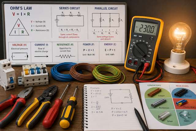
Introduction to Basic Electrical Principles
Basic electrical principles explain how electricity behaves in a circuit. Every electrical installation, whether simple or complex, depends on the relationship between voltage, current, resistance, power, energy, conductors, insulators, and circuit arrangement.
Understanding these principles helps electrical workers select the right cable size, choose protective devices, troubleshoot faults, avoid overloads, and install electrical systems safely.
Voltage, Current and Resistance
Voltage, current, and resistance are the three foundation concepts of electrical work.
| Term | Symbol | Unit | Meaning |
|---|---|---|---|
| Voltage | V | Volt | The electrical pressure that pushes current through a circuit |
| Current | I | Ampere | The flow of electric charge through a conductor |
| Resistance | R | Ohm | The opposition to the flow of current |
Voltage can be compared to water pressure in a pipe. Current is like the amount of water flowing, while resistance is anything that restricts or slows the flow.
In an electrical circuit, current flows when there is a complete path and a voltage source. If the path is broken, current cannot flow.
Voltage
Voltage is the force that pushes electric current through a circuit. Without voltage, there is no electrical pressure to move current.
Common examples include:
| Source | Typical Voltage |
|---|---|
| Small battery | 1.5 V DC |
| Car battery | 12 V DC |
| USB charger | 5 V DC |
| Household supply in many countries | 220–240 V AC |
| Industrial three-phase supply | Commonly 400–415 V AC |
High voltage can be very dangerous, but even lower voltages can cause harm under certain conditions, especially when the body is wet or contact is prolonged.
Current
Current is the actual flow of electric charge. It is measured in amperes.
A circuit with high current can generate heat, damage equipment, trip breakers, burn cables, or cause fire if the wiring and protection are not correctly designed.
There are two main types of current:
| Type | Meaning | Common Use |
|---|---|---|
| Direct Current: DC | Flows in one direction | Batteries, solar panels, electronics |
| Alternating Current: AC | Changes direction repeatedly | Homes, offices, factories, public supply |
Resistance
Resistance opposes the flow of current. The higher the resistance, the lower the current for a given voltage.
Resistance is affected by:
- Material type
- Length of conductor
- Cross-sectional area
- Temperature
- Condition of the connection
Longer cables have more resistance. Larger cables have lower resistance. Loose or corroded connections create unwanted resistance, which may cause overheating.
Ohm’s Law
Ohm’s Law explains the relationship between voltage, current, and resistance.
V = I × R
Where:
- V = Voltage in volts
- I = Current in amperes
- R = Resistance in ohms
The formula can also be rearranged:
| Formula | Use |
|---|---|
| V = I × R | To find voltage |
| I = V ÷ R | To find current |
| R = V ÷ I | To find resistance |
Example:
If a circuit has a voltage of 12 V and a resistance of 4 Ω:
I = V ÷ R
I = 12 ÷ 4
I = 3 A
So, the current flowing in the circuit is 3 amperes.
Ohm’s Law is useful for basic circuit analysis, fault finding, cable checks, and understanding how electrical loads behave.
Electrical Power
Electrical power is the rate at which electrical energy is used or converted into another form, such as light, heat, sound, or motion.
Power is measured in watts.
P = V × I
Where:
- P = Power in watts
- V = Voltage in volts
- I = Current in amperes
Example:
If an appliance operates at 230 V and draws 5 A:
P = 230 × 5
P = 1,150 W
The appliance uses 1,150 watts, or 1.15 kilowatts.
Electrical Energy
Electrical energy is the total amount of electricity used over time. It is commonly measured in kilowatt-hours, written as kWh.
Electricity bills are usually based on kilowatt-hours.
Energy = Power × Time
Example:
If a 1,000 W appliance runs for 3 hours:
1,000 W = 1 kW
1 kW × 3 hours = 3 kWh
So, the appliance consumes 3 kilowatt-hours of energy.
Difference Between Power and Energy
Power and energy are related, but they are not the same.
| Term | Meaning | Unit |
|---|---|---|
| Power | How fast electricity is being used | Watt or kilowatt |
| Energy | Total electricity used over time | Kilowatt-hour |
A high-power appliance uses more electricity quickly. The longer it operates, the more energy it consumes.
Series Circuits
A series circuit has components connected one after another in a single path. The same current flows through all components.
In a series circuit:
- Current is the same through all components.
- Total resistance increases as more components are added.
- Voltage is shared across the components.
- If one component fails open, the entire circuit stops working.
Example:
Old decorative lights are often wired in series. If one lamp fails, the whole string may go off.
Total Resistance in Series
R total = R1 + R2 + R3
If three resistors are connected in series:
- R1 = 2 Ω
- R2 = 4 Ω
- R3 = 6 Ω
Total resistance:
2 + 4 + 6 = 12 Ω
Parallel Circuits
A parallel circuit has components connected across the same supply points, creating more than one path for current.
In a parallel circuit:
- Voltage is the same across each branch.
- Current is divided between the branches.
- Total current increases as more branches are added.
- If one branch fails, other branches can still operate.
Most building circuits use parallel arrangements so that one light or appliance can work independently of another.
Total Resistance in Parallel
In a parallel circuit, total resistance is lower than the smallest branch resistance.
For two resistors:
1/R total = 1/R1 + 1/R2
Example:
If R1 = 6 Ω and R2 = 3 Ω:
1/R total = 1/6 + 1/3
1/R total = 1/6 + 2/6
1/R total = 3/6
R total = 2 Ω
Series vs Parallel Circuits
| Feature | Series Circuit | Parallel Circuit |
|---|---|---|
| Current | Same through all components | Divides across branches |
| Voltage | Shared across components | Same across each branch |
| Resistance | Increases when more loads are added | Decreases when more branches are added |
| Fault effect | One open fault stops all components | One faulty branch may not stop others |
| Common use | Simple control circuits, internal equipment circuits | Lighting, socket outlets, building wiring |
Conductors and Insulators
Electrical materials are commonly grouped as conductors or insulators.
A conductor allows current to flow easily. An insulator resists the flow of current.
Conductors
Conductors are materials with low resistance. They are used to carry electrical current.
Common conductors include:
- Copper
- Aluminium
- Steel, in some applications
- Brass
- Silver, in specialised applications
Copper is widely used in electrical wiring because it has good conductivity, flexibility, and reliability.
Aluminium is also used, especially for larger cables and overhead lines, but it requires correct installation practices because it behaves differently from copper.
Insulators
Insulators are materials that resist electrical current. They are used to protect people, separate conductors, and prevent short circuits.
Common insulators include:
- PVC
- Rubber
- Glass
- Porcelain
- Plastic
- Ceramic
- Dry wood, under limited conditions
Cable insulation must be in good condition. Damaged insulation can expose live conductors and create shock, short-circuit, or fire risk.
Semiconductor Materials
Some materials are neither good conductors nor good insulators. They are called semiconductors.
Examples include:
- Silicon
- Germanium
Semiconductors are used in electronic components such as diodes, transistors, solar cells, and integrated circuits.
Basic Circuit Analysis
Basic circuit analysis means studying a circuit to understand how voltage, current, resistance, and power behave.
A simple analysis should identify:
- The power source
- The load
- The conductors
- The switch or control device
- The protective device
- The current path
- Whether the circuit is series, parallel, or combined
- Expected voltage, current, resistance, and power values
Simple Circuit Analysis Steps
Start by asking these questions:
- Is the circuit complete?
- What is the supply voltage?
- What loads are connected?
- Are the loads in series or parallel?
- What is the total resistance?
- What current should flow?
- What power does the load consume?
- Is the cable size suitable?
- Is the protective device correctly rated?
- Are there signs of overload, loose connection, or damaged insulation?
This method helps electrical workers understand normal operation and identify possible faults.
Example of Basic Circuit Analysis
A 230 V lamp circuit has a lamp rated at 100 W.
To find the current:
P = V × I
Rearrange:
I = P ÷ V
So:
I = 100 ÷ 230
I = 0.43 A approximately
This means the lamp draws about 0.43 amperes during normal operation.
If the circuit breaker is 6 A, the lamp load is far below the breaker rating. However, cable size, installation method, number of loads, and regulations must still be considered before deciding whether the installation is safe.
Common Faults Related to Basic Electrical Principles
Many electrical faults can be understood using voltage, current, resistance, and power.
| Fault | Possible Cause |
|---|---|
| No power | Open circuit, tripped breaker, blown fuse, loose connection |
| Low voltage | Voltage drop, overload, poor connection, long cable run |
| Overheating cable | Overload, loose terminal, undersized cable |
| Tripping breaker | Short circuit, overload, earth fault, faulty appliance |
| Dim lights | Voltage drop, poor connection, overloaded circuit |
| Burning smell | Overheating, loose connection, insulation damage |
| Electric shock | Exposed live part, poor earthing, insulation failure |
Practical Safety Reminder
Basic electrical principles must always be applied with safety in mind. Never test or analyse live circuits unless you are trained, authorised, and using the correct equipment and PPE.
Before working on any circuit:
- Isolate the supply.
- Lock and tag where required.
- Test to confirm the circuit is dead.
- Use approved test instruments.
- Keep unauthorised people away.
- Follow site procedures and wiring regulations.
Common Mistakes in Basic Electrical Work
Avoid these mistakes:
- Confusing voltage with current.
- Ignoring resistance in long cable runs.
- Overloading circuits.
- Using the wrong cable size.
- Assuming all loads consume the same current.
- Ignoring power rating on appliances.
- Connecting loads incorrectly in series or parallel.
- Using damaged insulation.
- Making loose terminal connections.
- Testing resistance on a live circuit.
- Replacing protective devices with incorrect ratings.
What an Electrical Worker Should Never Do
An electrical worker should never:
- Work on a circuit without confirming isolation.
- Touch exposed live conductors.
- Guess current or load rating without calculation.
- Ignore overheating or burning smells.
- Use damaged cables or accessories.
- Bypass fuses, breakers, or protective devices.
- Overload sockets or extension leads.
- Use incorrect meter settings on live circuits.
- Leave conductors exposed after testing.
- Treat basic electrical calculations as optional.
Quick Recap
Basic electrical principles explain how circuits work. Voltage pushes current, current flows through conductors, and resistance opposes current. Ohm’s Law shows the relationship between voltage, current, and resistance, while power and energy explain how electrical loads use electricity. Series circuits have one current path, while parallel circuits have multiple paths. Conductors allow current to flow, while insulators prevent unwanted current flow. Understanding these principles is essential for safe installation, testing, troubleshooting, and maintenance.