
Electrical Drawings
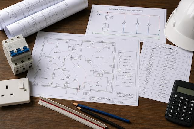
Introduction to Electrical Drawings
Electrical drawings are technical documents that show how an electrical installation should be planned, wired, connected, protected, and maintained. They help electricians, technicians, engineers, supervisors, and maintenance teams understand the layout and operation of an electrical system before work begins.
A good electrical drawing reduces guesswork. It shows where cables should run, where switches and sockets should be installed, how circuits are connected, and which protective devices serve each circuit.
Electrical drawings are used for:
- Planning new installations
- Understanding existing installations
- Installing lighting and power circuits
- Locating switches, sockets, panels, and equipment
- Troubleshooting faults
- Carrying out maintenance
- Communicating technical information clearly
Reading Electrical Drawings
Reading an electrical drawing means understanding the symbols, lines, labels, notes, and layout used to represent an electrical system.
Before interpreting any drawing, first check:
| Item | Why It Matters |
|---|---|
| Drawing title | Shows what the drawing is about |
| Drawing number | Helps identify the correct document |
| Revision number | Confirms the latest version |
| Scale | Shows the relationship between drawing size and real size |
| Legend | Explains symbols and abbreviations |
| Notes | Provides important installation instructions |
| Circuit labels | Identifies circuits and equipment |
| Cable sizes | Shows conductor rating and type |
| Distribution board reference | Shows where circuits originate |
| Date and approval | Confirms issue and authorisation status |
Never work from an outdated or unclear drawing. If a drawing does not match the site condition, stop and confirm before continuing.
Types of Electrical Drawings
Different electrical drawings serve different purposes.
| Drawing Type | Purpose |
|---|---|
| Wiring diagram | Shows how electrical components are connected |
| Layout drawing | Shows the physical location of electrical points |
| Single-line diagram | Shows the main electrical distribution in simplified form |
| Schematic diagram | Shows circuit operation using symbols |
| Installation plan | Shows how the work should be installed on site |
| Panel schedule | Shows circuit details in a distribution board |
| Cable schedule | Lists cable types, sizes, routes, and destinations |
| As-built drawing | Shows the final installed condition after completion |
Electrical Symbols
Electrical symbols are standard graphic signs used to represent electrical components on drawings. Instead of drawing a real switch, socket, lamp, or breaker, the drawing uses a symbol.
Common electrical symbols include:
| Symbol / Item | Meaning |
|---|---|
| Lamp / light point | Lighting outlet |
| One-way switch | Switch controlling one point from one location |
| Two-way switch | Switch used for control from two locations |
| Socket outlet | Power outlet for appliances |
| Distribution board | Panel supplying several circuits |
| Circuit breaker | Protective device against overload and short circuit |
| Fuse | Protective device that melts during excess current |
| Earth point | Connection to protective earth |
| Fan point | Ceiling or exhaust fan connection |
| Junction box | Point where cables are joined |
| Isolator | Local disconnection point |
| Conduit route | Path for cable containment |
| Cable tray | Support route for multiple cables |
Symbols may vary depending on the drawing standard, company practice, or country. Always check the drawing legend before interpreting symbols.
Lines and Labels on Electrical Drawings
Lines on electrical drawings may represent cables, conduits, wiring routes, control paths, or connections between components.
Common line meanings include:
| Line Type | Possible Meaning |
|---|---|
| Solid line | Main wiring or visible route |
| Dashed line | Hidden route, control link, or proposed work |
| Thick line | Main supply cable or major route |
| Thin line | Branch circuit or minor wiring route |
| Arrow line | Direction of supply, cable route, or signal flow |
| Dotted boundary | Equipment zone or panel boundary |
Labels give more detail about the circuit. A label may show cable size, circuit number, breaker rating, switch reference, equipment tag, or distribution board name.
Example:
DB-1 / L1 / 1.5mm² / 10A
This may indicate a lighting circuit from Distribution Board 1, using 1.5mm² cable and protected by a 10A breaker.
Wiring Diagrams
A wiring diagram shows how electrical components are connected together. It helps the installer understand which conductor goes where.
Wiring diagrams are useful for:
- Connecting switches
- Wiring sockets
- Installing lighting points
- Connecting control circuits
- Understanding equipment terminals
- Troubleshooting faults
A wiring diagram may show:
- Live conductor
- Neutral conductor
- Earth conductor
- Switch wire
- Load connection
- Terminal numbers
- Cable colours
- Protective device
- Control device
- Connection points
Reading a Simple Lighting Wiring Diagram
A basic lighting circuit usually includes:
| Component | Function |
|---|---|
| Supply live | Brings power to the circuit |
| Switch | Controls the light |
| Switch live | Carries power from switch to lamp |
| Neutral | Completes the circuit back to supply |
| Earth | Provides fault protection |
| Lamp holder | Holds and connects the lamp |
In many lighting circuits, the switch should control the live conductor, not the neutral. This ensures the lamp is not left live when switched off.
Reading a Socket Wiring Diagram
A socket wiring diagram shows how live, neutral, and earth conductors are connected to the socket outlet.
The basic connections are:
| Terminal | Connection |
|---|---|
| L | Live conductor |
| N | Neutral conductor |
| E / Earth symbol | Protective earth conductor |
A socket must be wired with correct polarity. Reversed live and neutral can create a dangerous condition, even if the socket appears to work.
Layout Drawings
A layout drawing shows the physical location of electrical items in a building or work area. It is usually drawn over an architectural floor plan.
Layout drawings show where to install:
- Switches
- Socket outlets
- Light points
- Distribution boards
- Isolators
- Fans
- Cable routes
- Conduits and trunking
- Outdoor fittings
- Equipment connection points
A layout drawing helps the installer know where each electrical point should be placed. It also helps estimate cable lengths, plan routes, avoid clashes, and maintain neat installation work.
Common Information on Layout Drawings
Electrical layout drawings may include:
| Information | Purpose |
|---|---|
| Room names | Identifies location |
| Mounting height | Shows installation height |
| Circuit reference | Links point to a distribution board circuit |
| Switch control | Shows which switch controls which light |
| Socket rating | Shows load capacity |
| Cable route | Guides installation path |
| Equipment location | Shows where fixed appliances are installed |
| Legend | Explains symbols |
| Notes | Provides special instructions |
Installation Plans
An installation plan explains how electrical work should be carried out on site. It may combine layout drawings, wiring diagrams, material schedules, safety notes, and work instructions.
An installation plan helps workers understand:
- What is to be installed
- Where it should be installed
- What materials are required
- Which circuits supply each area
- What cable sizes to use
- What protective devices are required
- What containment method should be used
- What safety steps must be followed
- What testing should be done after installation
Using Electrical Drawings on Site
Before starting work, compare the drawing with the actual site.
Check:
- Wall positions
- Door swings
- Ceiling type
- Existing cables
- Pipework
- Structural beams
- Wet areas
- Equipment positions
- Distribution board location
- Cable route access
- Client or project requirements
If the drawing does not match the site condition, do not make assumptions. Report the issue and get clarification.
Drawing Revisions
Electrical drawings may change during a project. A revision is an updated version of the drawing.
Revisions may happen because of:
- Design changes
- Site conditions
- Client requests
- Equipment changes
- Safety corrections
- Load changes
- Routing changes
Always check the revision number before working. Using an old drawing can lead to wrong installation, wasted materials, unsafe wiring, and rework.
As-Built Drawings
An as-built drawing shows the final installation as it was actually completed.
This is important because installations may change during construction. Maintenance teams rely on as-built drawings to find circuits, trace cables, identify panels, and repair faults safely.
Good as-built drawings should show:
- Final cable routes
- Actual socket and switch locations
- Distribution board details
- Circuit numbers
- Protective device ratings
- Earthing details
- Equipment connections
- Any changes from the original design
Basic Drawing Abbreviations
Electrical drawings often use abbreviations to save space.
| Abbreviation | Meaning |
|---|---|
| DB | Distribution Board |
| MDB | Main Distribution Board |
| SMDB | Sub-Main Distribution Board |
| MCB | Miniature Circuit Breaker |
| MCCB | Moulded Case Circuit Breaker |
| RCCB | Residual Current Circuit Breaker |
| RCD | Residual Current Device |
| RCBO | Residual Current Breaker with Overcurrent Protection |
| L | Live |
| N | Neutral |
| E | Earth |
| SW | Switch |
| S/O | Socket Outlet |
| JB | Junction Box |
| EL | Emergency Light |
| AC | Air Conditioner / Alternating Current, depending on context |
| PVC | Polyvinyl Chloride |
| GI | Galvanised Iron |
Always interpret abbreviations based on the drawing legend and project context.
Practical Example
An electrical layout drawing shows two socket outlets in a room, one light point, and one switch near the door. The wiring diagram shows that the light is supplied from DB-1 circuit L1, while the sockets are supplied from DB-1 circuit P2.
The correct interpretation is that the lighting and socket circuits are separate. The installer should not connect the sockets to the lighting circuit simply because they are in the same room.
This is why drawings must be read carefully before installation starts.
Common Mistakes When Reading Electrical Drawings
Avoid these mistakes:
- Ignoring the drawing legend.
- Working from an old drawing revision.
- Confusing layout drawings with wiring diagrams.
- Assuming symbols without confirmation.
- Ignoring circuit labels.
- Misreading cable sizes.
- Installing points at the wrong height.
- Connecting equipment to the wrong circuit.
- Ignoring drawing notes.
- Failing to update as-built drawings.
- Not checking site conditions before installation.
- Assuming all projects use the same symbols.
What an Electrical Worker Should Never Do
An electrical worker should never:
- Start installation without checking the drawing.
- Work from an outdated drawing.
- Ignore drawing notes and legends.
- Change cable routes without approval.
- Install a circuit without confirming its source.
- Guess symbols or abbreviations.
- Mix up live, neutral, and earth connections.
- Ignore discrepancies between drawing and site.
- Leave changes undocumented.
- Assume a drawing is correct without site verification.
- Energise an installation without inspection and testing.
Quick Recap
Electrical drawings help workers understand how an installation should be wired, arranged, connected, and maintained. Common drawings include wiring diagrams, layout drawings, installation plans, single-line diagrams, and as-built drawings. To read drawings correctly, always check the title, revision, symbols, legend, notes, circuit labels, and site condition. Good drawing interpretation improves safety, accuracy, speed, and quality of electrical installation work.