
Industrial Control Panels
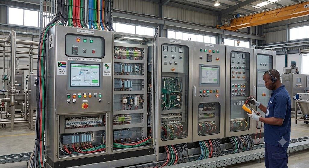
Introduction to Industrial Control Panels
An industrial control panel is an enclosure that houses electrical and control components used to operate, protect, monitor, and automate machines or process systems.
Control panels are used in factories, oil and gas facilities, power plants, water treatment plants, marine systems, HVAC systems, packaging lines, pumping stations, process plants, and industrial workshops.
A control panel may control a single motor, a pump system, a production machine, a PLC system, or a complete process unit. It may contain components such as breakers, fuses, contactors, relays, power supplies, PLC modules, terminal blocks, signal isolators, VFDs, HMIs, and communication devices.
Industrial control panels must be designed, wired, labelled, protected, installed, inspected, and maintained properly because poor panel work can lead to equipment damage, fire, electric shock, arc flash, production shutdown, or unsafe machine operation.
Why Industrial Control Panels Are Important
Industrial control panels act as the organised connection point between field devices, electrical power, control logic, operators, and machines.
They are important because they help to:
- Distribute power safely.
- Protect circuits from overload and short circuit.
- Control motors, pumps, fans, valves, heaters, and actuators.
- Receive signals from instruments and sensors.
- Send commands to field devices.
- House PLCs and control modules.
- Provide manual and automatic control.
- Support alarms, interlocks, and trips.
- Improve troubleshooting and maintenance.
- Provide a neat and safe wiring arrangement.
- Protect components from dust, moisture, impact, and accidental contact.
A good control panel makes the control system safer, easier to maintain, and more reliable.
Main Functions of an Industrial Control Panel
An industrial control panel may perform several functions depending on the system design.
| Function | Description |
|---|---|
| Power control | Supplies and distributes power to equipment |
| Circuit protection | Protects cables and devices from faults |
| Motor control | Starts, stops, reverses, or controls motor speed |
| Process control | Receives process signals and sends control outputs |
| Automation | Runs PLC logic, sequences, and interlocks |
| Signal termination | Provides organised connection points for field wiring |
| Operator control | Provides push buttons, selector switches, lamps, or HMI |
| Communication | Connects PLC, HMI, SCADA, drives, meters, and remote I/O |
| Safety | Supports emergency stop, trips, alarms, and protective circuits |
Common Types of Control Panels
Different control panels are used for different applications.
| Panel Type | Common Use |
|---|---|
| PLC panel | Houses PLC, I/O modules, power supply, and signal wiring |
| Motor control panel | Controls motors, pumps, fans, and compressors |
| VFD panel | Houses variable frequency drives for motor speed control |
| MCC panel | Motor Control Centre for multiple motors |
| HMI panel | Provides operator display and control interface |
| Distribution panel | Distributes electrical power to circuits |
| Instrument panel | Houses indicators, controllers, barriers, and signal devices |
| Control desk / console | Operator control station |
| Junction box | Field cable termination and distribution |
| Local control station | Field-mounted start/stop and control devices |
A plant may use several panel types working together.
Control Panel Enclosure
The enclosure is the outer box that protects the control components. It may be made from mild steel, stainless steel, aluminium, or non-metallic materials depending on the environment.
The enclosure protects against:
- Accidental contact
- Dust
- Moisture
- Chemicals
- Mechanical impact
- Heat
- Corrosion
- Unauthorized access
The enclosure must be suitable for the location. A panel installed outdoors or near water requires stronger environmental protection than a panel installed inside a clean control room.
Panel Rating and Environment
Panel selection should consider the operating environment.
Important factors include:
- Indoor or outdoor installation
- Dust exposure
- Water exposure
- Corrosive atmosphere
- Ambient temperature
- Sunlight exposure
- Vibration
- Hazardous area classification
- Washdown requirement
- Ventilation or cooling need
- Access for maintenance
A panel installed in a harsh environment should have proper sealing, gland plates, cable entries, ventilation, corrosion protection, and enclosure rating.
Main Components Inside a Control Panel
A typical control panel may contain several electrical and control components.
| Component | Function |
|---|---|
| Main isolator | Disconnects incoming power |
| Circuit breaker | Protects against overload and short circuit |
| Fuse | Protects circuits and devices |
| Contactor | Switches motor or load circuits |
| Overload relay | Protects motors from overload |
| Control relay | Performs switching in control circuits |
| Timer relay | Provides time delay functions |
| Power supply | Converts AC to DC, commonly 24 V DC |
| PLC CPU | Executes control logic |
| PLC I/O modules | Receive inputs and send outputs |
| Terminal blocks | Provide wiring termination points |
| Signal isolator | Isolates and conditions signals |
| Surge protection device | Protects against voltage surges |
| VFD | Controls motor speed |
| HMI | Provides operator interface |
| Ethernet switch | Supports industrial communication |
| Earthing bar | Provides protective earth connection |
| Cable trunking | Organises wiring |
| Cooling fan/filter | Helps manage panel temperature |
Not every panel contains all these parts. The contents depend on the application.
Main Isolator
The main isolator is used to disconnect the panel from its incoming electrical supply. It allows authorised personnel to isolate power before inspection, maintenance, or repair.
A main isolator should be clearly labelled and accessible. In many installations, it may be lockable so that Lockout/Tagout can be applied during maintenance.
OSHA’s Lockout/Tagout requirements focus on disabling machinery or equipment and preventing unexpected energisation, start-up, or release of hazardous energy during servicing or maintenance.
Circuit Breakers
Circuit breakers protect electrical circuits from overload and short-circuit faults. When the current exceeds a safe limit, the breaker trips and disconnects the circuit.
Circuit breakers are used to protect:
- Incoming supply circuits
- Motor circuits
- Control circuits
- Power supplies
- PLC circuits
- Instrument circuits
- Panel lighting and sockets
- Auxiliary devices
A breaker should be correctly rated for the circuit it protects. An oversized breaker may fail to protect the wiring properly.
Fuses
A fuse protects a circuit by melting when current becomes too high. Once it operates, it must be replaced.
Fuses are commonly used for:
- Control transformers
- Power supplies
- Instrument loops
- PLC circuits
- Drives
- Solenoid circuits
- Small control circuits
The replacement fuse must match the correct rating and type. Never replace a fuse with wire, foil, or an oversized fuse.
Contactors
A contactor is an electrically operated switch used to control power to motors and other loads.
Contactors are commonly used for:
- Starting motors
- Stopping motors
- Controlling pumps
- Controlling fans
- Switching heaters
- Operating compressors
- Switching lighting or industrial loads
A contactor has a coil and power contacts. When the coil is energised, the contacts close and supply power to the load.
Overload Relays
An overload relay protects a motor from sustained overload current. It does not replace short-circuit protection; it works together with breakers or fuses.
If a motor draws too much current for too long, the overload relay trips and stops the motor.
Common causes of overload include:
- Mechanical jam
- Pump blockage
- Bearing failure
- Overloading
- Phase loss
- Incorrect motor sizing
- Poor ventilation
- Low voltage
After an overload trip, the cause should be investigated before resetting.
Control Relays
Control relays are used to switch control signals. They allow one circuit to control another circuit.
Relays may be used for:
- Signal multiplication
- Interlocking
- Alarm logic
- Motor control
- Start/stop circuits
- Interface between PLC and field devices
- Electrical isolation between circuits
Relay contacts may be normally open or normally closed. The correct contact type must be used based on the control logic.
Timer Relays
Timer relays provide time delays in control circuits.
They may be used for:
- Motor start delay
- Star-delta transition
- Alarm delay
- Pump changeover
- Fan run-on time
- Sequence control
- Delay before shutdown
- Delay before restart
Timer settings should be documented because wrong timing can affect machine operation and safety.
Power Supplies
Many control panels use a DC power supply to provide control voltage, commonly 24 V DC.
A power supply may feed:
- PLC CPU
- I/O modules
- Sensors
- Transmitters
- Relays
- Solenoids
- HMI
- Signal isolators
- Communication devices
A poor or overloaded power supply can cause intermittent faults, PLC resets, unstable signals, or device failure.
Transformers
A transformer changes AC voltage from one level to another. In control panels, transformers may be used to provide lower control voltage from a higher supply voltage.
Examples:
- 415 V AC to 230 V AC
- 230 V AC to 110 V AC
- 230 V AC to 24 V AC
Transformers should be correctly rated, protected, wired, and labelled.
PLC Components in Control Panels
A PLC panel may include:
- PLC CPU
- Digital input modules
- Digital output modules
- Analog input modules
- Analog output modules
- Communication modules
- Power supply
- Remote I/O interface
- Memory card or backup module
- Communication cables
PLC components should be arranged neatly and kept away from excessive heat, moisture, vibration, and electrical noise.
Input and Output Modules
Input and output modules connect the PLC to field devices.
| Module Type | Signal Direction | Example |
|---|---|---|
| Digital input | Field to PLC | Push button, limit switch, pressure switch |
| Digital output | PLC to field | Relay, solenoid, lamp, contactor |
| Analog input | Field to PLC | 4–20 mA pressure transmitter |
| Analog output | PLC to field | 4–20 mA valve position command |
Each module must match the signal type and voltage/current rating of the connected device.
Terminal Blocks
Terminal blocks provide safe and organised connection points for wires.
They are used to connect:
- Field cables
- PLC inputs and outputs
- Control circuits
- Instrument loops
- Power supply circuits
- Earth connections
- Communication cables
Good terminal work makes troubleshooting easier. Loose or poorly tightened terminals can cause intermittent faults, heating, voltage drop, signal loss, or equipment malfunction.
Marshalling Terminals
Marshalling terminals are used to organise field wiring before connecting signals to PLC, DCS, or other control equipment.
A marshalling section may include:
- Field cable terminals
- Signal terminals
- Fuse terminals
- Disconnect terminals
- Relay interfaces
- Signal isolators
- Barriers
- Earthing terminals
- Shield terminals
Marshalling helps separate field wiring from internal panel wiring and improves maintenance access.
Signal Isolators
Signal isolators protect and separate instrument signals. They help reduce noise, prevent ground-loop problems, and protect control system inputs.
Signal isolators may be used for:
- 4–20 mA signals
- 0–10 V signals
- RTD signals
- Thermocouple signals
- Digital signals
- Hazardous-area interfaces
A signal isolator must be selected for the correct signal type and powered correctly.
Intrinsic Safety Barriers
Intrinsic safety barriers are used in hazardous-area instrumentation systems to limit electrical energy going into hazardous areas.
They may be used for:
- Transmitters
- Switches
- Solenoid valves
- Temperature sensors
- Field instruments in classified areas
Barriers must be installed, wired, earthed, and maintained according to the hazardous-area design and approved documentation.
Surge Protection Devices
Surge protection devices protect electrical and control circuits from voltage surges caused by lightning, switching transients, or electrical disturbances.
They may be installed on:
- Incoming power lines
- Instrument signal lines
- Communication cables
- Outdoor field wiring
- Power supply circuits
Surge protection is especially important for outdoor equipment, long cable runs, and exposed industrial sites.
Variable Frequency Drives
A Variable Frequency Drive, or VFD, controls motor speed by changing the frequency and voltage supplied to the motor.
VFDs are commonly used for:
- Pumps
- Fans
- Blowers
- Compressors
- Conveyors
- HVAC systems
- Process control applications
VFDs can improve energy efficiency and process control, but they must be wired, cooled, earthed, and protected correctly.
HMI in Control Panels
An HMI, or Human-Machine Interface, allows operators to monitor and control the system.
An HMI may display:
- Equipment status
- Process values
- Alarms
- Setpoints
- Trends
- Start/stop buttons
- Manual/automatic selection
- Fault messages
- Maintenance information
The HMI should be clear, user-friendly, and protected from dust, moisture, and physical damage.
Communication Devices
Modern control panels often include communication devices.
Examples include:
- Ethernet switches
- Serial converters
- Modbus gateways
- Profibus connectors
- Profinet switches
- Fibre converters
- Remote I/O adapters
- Wireless gateways, where allowed
Communication wiring should be routed carefully, labelled clearly, and separated from high-power cables where required.
Control Panel Wiring
Good wiring is one of the most important parts of control-panel quality.
Good wiring practice includes:
- Use correct cable size.
- Use correct wire colour according to site standard.
- Use ferrules where required.
- Tighten terminals properly.
- Route wires neatly inside trunking.
- Separate power and signal wiring where possible.
- Label wires clearly at both ends.
- Avoid sharp bends and cable damage.
- Do not overcrowd trunking.
- Keep spare cores safely terminated.
- Use correct glands for incoming cables.
- Maintain good earth continuity.
- Follow drawings and approved standards.
Poor wiring can cause faults that are difficult to trace.
Wire Labelling
Wire labels help technicians identify circuits quickly and safely.
Good labelling should include:
- Wire number
- Terminal number
- Device tag
- Panel reference
- Circuit reference
- Cable number where applicable
Labels should be readable, durable, and consistent with drawings.
A wire without a label may waste hours during troubleshooting.
Panel Component Labelling
Panel components should be labelled clearly.
Items that should be labelled include:
- Main isolator
- Breakers
- Fuses
- Contactors
- Relays
- PLC modules
- Power supplies
- Terminals
- HMI
- VFD
- Signal isolators
- Communication devices
- Earth bar
- Incoming and outgoing cables
Labels help with operation, maintenance, inspection, and safety.
Panel Layout
Panel layout affects safety, access, cooling, wiring quality, and maintenance.
Good layout practice includes:
- Keep high-voltage and low-voltage sections separated where possible.
- Keep power devices away from sensitive signal devices.
- Provide enough space for wiring and maintenance.
- Keep heat-generating devices properly ventilated.
- Mount frequently accessed devices where they are easy to reach.
- Allow space for cable entry and gland plates.
- Keep terminals accessible.
- Avoid overcrowding.
- Arrange components logically.
- Consider future expansion where possible.
A neat panel is not only attractive; it is easier and safer to troubleshoot.
Separation of Power and Signal Wiring
Power cables can produce electrical noise that affects sensitive signals.
Good separation practice includes:
- Route power cables separately from signal cables.
- Keep VFD motor cables away from analog signal cables.
- Cross power and signal cables at right angles where crossing is unavoidable.
- Use shielded cables where specified.
- Earth shields according to project standards.
- Avoid running thermocouple or RTD cables near power circuits.
- Keep communication cables away from high-current cables.
Poor cable separation can cause unstable analog readings, communication faults, and false alarms.
Earthing and Grounding
Earthing provides a safe path for fault current and helps reduce electrical noise when designed correctly.
In a control panel, earthing may include:
- Protective earth
- Panel enclosure earth
- Door bonding
- DIN rail bonding
- Cable gland earth
- Shield earth
- Instrument earth
- Clean earth, where specified
- VFD earth
NFPA 70E focuses on reducing exposure to electrical hazards such as shock, arc flash, and arc blast, while OSHA Lockout/Tagout requirements address control of hazardous energy during servicing and maintenance.
Shielding
Shielding protects signal cables from electrical noise. It is especially important for:
- Analog signals
- RTD signals
- Thermocouple signals
- Communication cables
- Low-level instrument signals
- VFD-adjacent wiring
Shielding must be connected according to the project or manufacturer’s standard. Wrong shielding can create noise problems instead of solving them.
Panel Cooling and Ventilation
Control panels can become hot due to power supplies, VFDs, transformers, PLCs, relays, and surrounding environmental temperature.
Heat can reduce component life and cause failures.
Cooling methods include:
- Natural ventilation
- Fans and filters
- Air conditioners
- Heat exchangers
- Panel spacing
- Heat sinks
- Proper component arrangement
Filters should be cleaned or replaced regularly. A blocked filter can cause panel overheating.
Panel Lighting and Service Sockets
Some panels include internal lighting and service sockets for maintenance support.
Panel lighting helps technicians inspect and work safely inside the enclosure.
Service sockets should be properly protected and used according to site rules. They should not be overloaded or used for unauthorised equipment.
Panel Drawings
Panel drawings are essential for understanding, operating, and maintaining control panels.
Important drawings include:
- General arrangement drawing
- Power wiring diagram
- Control wiring diagram
- PLC I/O wiring diagram
- Terminal schedule
- Cable schedule
- Loop diagram
- Network diagram
- Bill of materials
- Panel layout drawing
- Earthing diagram
- Cause and effect chart, where applicable
Technicians should always compare the panel with the latest approved drawings before making changes.
Control Panel Standards
Industrial control panels should be designed and built according to recognised standards and local regulations.
Examples of relevant standards and references include:
| Standard / Reference | Common Relevance |
|---|---|
| UL 508A | Industrial control panels |
| NFPA 70 / NEC | Electrical installation requirements in the United States |
| NFPA 70E | Electrical safety in the workplace |
| IEC 60204-1 | Electrical equipment of machines |
| IEC 61439 | Low-voltage switchgear and controlgear assemblies |
| OSHA LOTO requirements | Control of hazardous energy during maintenance |
| Local electrical codes | National or regional legal requirements |
UL describes UL 508A as the Standard for Industrial Control Panels, and its summary helps users determine a path to compliance with revised requirements.
Short Circuit Current Rating
Short Circuit Current Rating, or SCCR, is the maximum short-circuit current a panel or equipment can safely withstand under specified conditions.
SCCR is important because a panel must be able to safely handle the available fault current at the installation point.
If a panel’s SCCR is lower than the available fault current, the panel may fail dangerously during a short circuit.
Panel builders and qualified designers must calculate and label SCCR correctly according to the applicable standard.
Control Panel Inspection
Control panels should be inspected before energisation, during commissioning, and during maintenance.
Inspection should check:
- Correct panel identification
- Proper enclosure condition
- Correct component installation
- Correct wire size and colour
- Tight terminals
- Correct labels
- Correct earthing and bonding
- Correct fuse and breaker ratings
- Correct cable glands
- No loose wires
- No damaged insulation
- No tools or foreign materials inside
- Correct separation of power and signal wiring
- Correct drawings available
- No signs of overheating
- Clean filters and ventilation
- Door seals in good condition
Inspection prevents many avoidable faults.
Pre-Energisation Checks
Before energising a panel, the technician should confirm that the panel is safe and ready.
Checks may include:
- Confirm drawings and panel tag.
- Confirm incoming supply voltage.
- Verify isolation and safety clearance.
- Check earth continuity.
- Check insulation resistance where required.
- Check terminal tightness.
- Check fuse and breaker ratings.
- Check power supply output setting.
- Check polarity of DC circuits.
- Check PLC and module seating.
- Check field cables are terminated correctly.
- Check no tools are left inside.
- Confirm covers and barriers are installed.
- Inform responsible personnel before energising.
Energising a panel without proper checks can damage equipment or injure people.
Commissioning a Control Panel
Commissioning confirms that the panel works correctly after installation.
Commissioning activities may include:
- Visual inspection
- Power supply check
- Earth continuity test
- Insulation resistance test
- Point-to-point wiring check
- PLC power-up check
- I/O check
- Signal simulation
- HMI check
- Motor rotation check
- Interlock test
- Alarm test
- Trip test
- Communication test
- Functional test
- Documentation update
Commissioning should be performed using approved procedures and proper records.
Routine Maintenance
Routine maintenance helps keep control panels safe and reliable.
Common maintenance activities include:
- Visual inspection
- Cleaning dust carefully
- Checking for moisture
- Checking door seals
- Checking cooling fans
- Cleaning or replacing filters
- Checking terminal tightness
- Inspecting for heat marks
- Checking power supply output
- Checking battery condition where applicable
- Checking PLC fault logs
- Checking communication status
- Checking labels and drawings
- Checking earth connections
- Testing alarms and lamps where required
Maintenance frequency depends on environment, criticality, manufacturer recommendation, and site procedure.
Common Control Panel Faults
| Fault | Possible Cause |
|---|---|
| Panel has no power | Main isolator off, breaker trip, blown fuse, supply fault |
| PLC not running | Power supply fault, CPU fault, program fault, module fault |
| Input not changing | Field device fault, wiring fault, loose terminal, wrong module |
| Output not working | Faulty relay, blown fuse, interlock active, output module fault |
| Motor not starting | Overload trip, contactor fault, missing permissive, breaker trip |
| VFD fault | Overload, overtemperature, wiring fault, motor issue |
| HMI blank | Power fault, communication fault, screen failure |
| Communication lost | Cable fault, network fault, wrong address, failed switch |
| Panel overheating | Blocked filter, fan failure, high ambient temperature |
| Intermittent fault | Loose terminal, vibration, moisture, poor power supply |
| Analog value unstable | Noise, shielding fault, bad grounding, loose terminal |
| Fuse keeps blowing | Short circuit, wrong fuse rating, device fault |
A fault should be investigated logically before replacing components.
Troubleshooting Control Panels
A good troubleshooting process includes:
- Understand the complaint.
- Check alarms and HMI messages.
- Confirm panel power status.
- Check breakers, fuses, and isolators.
- Check PLC status lights.
- Check power supply output.
- Check field devices.
- Check input and output status.
- Check relay and contactor operation.
- Check wiring and terminals.
- Check communication devices.
- Check drawings and terminal schedules.
- Check interlocks and permissives.
- Document the fault and correction.
Do not guess. A systematic approach saves time and prevents unnecessary component replacement.
Control Panel Safety
Control panels can contain dangerous voltages, stored energy, rotating-machine controls, live terminals, and arc-flash hazards. Safety must always come first.
Safe work practices include:
- Only authorised persons should work on panels.
- Wear required PPE.
- Follow permit-to-work procedure where required.
- Apply Lockout/Tagout before maintenance where required.
- Verify absence of voltage before touching conductors.
- Use insulated tools.
- Keep one hand away where practical during testing.
- Stand on suitable insulation where required.
- Do not bypass protective devices.
- Do not work in wet conditions.
- Keep panel doors closed when not working.
- Never leave exposed live parts unattended.
- Report damaged components.
Electrical hazards can include shock, arc flash, and arc blast, and NFPA 70E provides requirements and guidance to reduce these workplace risks.
Lockout/Tagout for Control Panels
Lockout/Tagout, or LOTO, is used to prevent unexpected energisation or release of hazardous energy during maintenance.
Basic LOTO principles include:
- Identify all energy sources.
- Inform affected personnel.
- Shut down equipment properly.
- Isolate energy sources.
- Apply lock and tag.
- Release stored energy.
- Verify zero energy state.
- Perform work safely.
- Remove tools and personnel.
- Restore energy only after proper checks and authorisation.
OSHA explains that Lockout/Tagout practices and procedures are used to disable machinery or equipment and prevent hazardous energy release during servicing and maintenance.
Stored Energy
Even after a panel is switched off, stored energy may remain.
Stored energy may be present in:
- Capacitors
- VFD DC bus
- UPS systems
- Batteries
- Pneumatic systems
- Hydraulic systems
- Springs
- Rotating equipment
- Charged cables
Always wait for discharge time where required and verify with a suitable test instrument.
Panel Housekeeping
Good housekeeping improves safety and reliability.
A control panel should not contain:
- Loose wires
- Unused screws
- Tools
- Cable offcuts
- Dust buildup
- Oil or water
- Paper documents left near hot components
- Unlabelled temporary wiring
- Insects or foreign materials
- Broken cable ties
- Open trunking covers
A dirty or poorly maintained panel can lead to overheating, tracking, short circuits, and difficult troubleshooting.
Documentation and Change Control
Any change made to a panel should be documented.
Changes may include:
- New wiring
- Removed wiring
- Replaced components
- Changed relay logic
- Changed PLC module
- Changed fuse or breaker rating
- Added instruments
- Modified terminal connections
- Changed labels
- Updated drawings
Never make undocumented changes. The next technician may depend on the drawing during an emergency or breakdown.
Real-Life Scenario
A pump fails to start from the control room. The operator says the PLC panel is faulty. The technician opens the panel after following safety procedures and checks the HMI alarm. The alarm shows “Motor Overload Trip.”
The technician checks the motor starter section and finds that the overload relay has tripped. Further inspection shows that the pump was mechanically jammed.
The control panel was not the root problem. The panel protected the motor from damage by stopping the circuit. A good technician investigates both the panel and the field equipment before replacing components.
Common Beginner Mistakes
Avoid these mistakes:
- Working inside a panel without isolation.
- Assuming 24 V DC panels are completely safe.
- Replacing fuses with the wrong rating.
- Ignoring loose terminals.
- Mixing power and signal wiring carelessly.
- Leaving panel doors open after work.
- Not checking drawings before troubleshooting.
- Forgetting to check breaker and fuse status.
- Ignoring earth connections.
- Leaving tools inside the panel.
- Bypassing overloads or trips.
- Resetting overloads repeatedly without finding the cause.
- Making wiring changes without updating drawings.
- Ignoring panel ventilation and blocked filters.
- Blaming the PLC before checking field devices.
What an Instrumentation Technician Should Never Do
An instrumentation technician should never:
- Work on live panels without authorisation and proper controls.
- Bypass protective devices casually.
- Replace a fuse with wire or an oversized fuse.
- Leave exposed live terminals uncovered.
- Ignore signs of overheating or burning smell.
- Change wiring without documentation.
- Disconnect wires without labelling them.
- Force PLC outputs without informing operations.
- Leave temporary jumpers inside the panel.
- Ignore arc-flash and shock hazards.
- Reset trips repeatedly without investigating the cause.
- Leave a panel dirty, open, or unsafe after work.
Quick Recap
Industrial control panels house the electrical and control components used to operate, protect, monitor, and automate industrial systems. They may contain breakers, fuses, contactors, overload relays, relays, power supplies, PLC modules, terminals, signal isolators, VFDs, HMIs, and communication devices. Good panel work requires correct wiring, labelling, layout, earthing, shielding, cooling, inspection, documentation, and safe maintenance. Control panels must be treated as potentially hazardous because they may contain dangerous voltage, stored energy, and arc-flash risk. A professional instrumentation technician must follow safety procedures, use drawings, troubleshoot logically, document changes, and never bypass protection or work carelessly inside a panel.